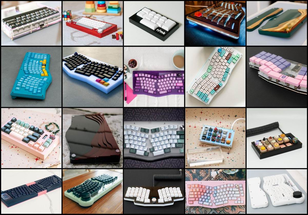
Keyboard Builders' Digest /
Building keyboards with lasers
Ming-Gih Lam walks through the process of how to build keyboard cases using vector graphics software and a laser cutter.

Published December 4, 2023
Introduction
I’m a software developer who’s been deeply involved in open-source keyboard projects since the pandemic hit. The struggle of trying to purchase a custom keyboard during that time due to limited supply led me to dive into building my own. I started by cloning open-source PCBs from GitHub and studied their construction with the help of online tutorials.
I learned how to use KiCad (open-source software used to design PCBs) by modifying existing designs. This consisted of adding features like a rotary encoder, extra keys, and upgrading USB ports to use Type-C – just for practice. Once I felt confident in my KiCad skills, I ventured into crafting PCBs entirely from scratch, tailored to my preferred layout.
However, despite these achievements, one significant challenge remained: creating the case. I was captivated by the cases designed by Qlavier and Switch Couture, particularly their sleekness and versatility of using stacked acrylic. This inspired me to invest in a laser cutter to try my hand at crafting similar cases myself. The added benefit? No need for complex 3D software – just good old 2D vector graphics which I was already familiar with.
Over the last 2 years, I’ve truly enjoyed building my own keyboards. I make everything I create open-source, because I know the frustration of finding something you really love, only to discover that it’s sold out, or that you’ve missed the group buy. I’m also quite excited to share some of the things I’ve learned during this journey, especially with regards to laser cutting. This article is by no means a comprehensive tutorial, but it should provide enough information to establish a foundational understanding of what it takes to design and construct your own keyboard case with acrylic.
Laser Cutter Basics
Let's start with some basics in case you're eyeing ownership or just curious about the machines suitable for the job. Firstly, ensure your machine operates with a CO2 laser. Diode lasers function differently and might serve some purposes well, but they lack the cutting power needed for most acrylics commonly used in keyboard cases. For optimal performance, I'd suggest a CO2 laser of at least 40 watts if you intend to cut 3mm thick acrylic, like the ones I use. Checking your laser's power saves frustration and material wastage down the road. Opting for a larger laser tube (ie. more wattage) not only ensures smooth glassy edges, but also enables cutting thicker acrylic.

Make sure to consider the cutting area size, which will depend on your case designs. I'd recommend a machine supporting a minimum width of 20 inches. This comfortably accommodates 80% cases but falls short for full-sized 100% cases. There are workarounds, however. Take my MidEvil case, for instance; I had to split the design into two halves and later join them, using colored acrylic pieces in between to conceal the seams. It turned out to add an aesthetic touch, but aligning everything perfectly during the gluing stage was quite challenging.

Apart from these factors, additional features like cameras, auto-adjustments, and customer support for the machine can save you time, but generally shouldn't hinder your ability to craft a case for your dream layout.
Designing “The Stack”
This step is arguably the most crucial one. Finding out your case is too small or that you don’t have enough acrylic to recut bad layers could really throw a wrench in your project. Think of it as an embodiment of 'measure twice, cut once' – it absolutely applies here.
First thing to consider is how you want to mount your PCB. For that, I’ll list a few options which vary in difficulty level:
- Sandwich mount: This is the easiest since one layer of your case will simply be the plate. Keep in mind that switches will only “snap” into 1.5mm plates. For thicker plates (ie. 3mm), switches will be held in by friction only, and may become loose if they’re not soldered to the PCB.
- Gasket mount: Two layers of acrylic, and usually some foam, will clamp your PCB (or plate) in place.
- Tray mount: This will not be the traditional tray mount since you can’t install threaded inserts into the bottom layer of the case. Instead, you’ll need the screw + standoff to poke completely out of the bottom layer, and rely on case foam to fill in the gap and hold the PCB up.
Once you've settled on the mounting method, fire up your vector graphics editor – I use Adobe Illustrator, but Inkscape is a good free option. Make sure your units are set to millimeters and begin sketching the cross-section of your keyboard using actual measurements. It's crucial for the height to be to scale, whereas the width is less critical as the focus is on vertical spacing. The aim is to generate adequate internal space within the case to accommodate all keyboard components while concealing any keycap gaps.
Here are a few examples of stack diagrams I use for cases designed with 2.8mm thick acrylic. There is some variance to the thickness of acrylic sheets (usually around ±15%), and in my experience, sheets labeled “3mm (⅛ inch)” are usually around 2.8mm minimum. I tend to err on the low side for the acrylic layers because too much space is generally better than too little. To be certain, you can easily measure the sheets (minus the masking) with digital calipers, an essential tool for these projects.

Be mindful of PCB components that protrude the most, typically the hotswap sockets or switch pins, along with the USB port. Other components like microcontroller development boards and OLED/LCD displays also demand significant vertical space, requiring careful consideration when creating cutouts to accommodate them.
It's important to note that even if a component occupies only a few layers, it can still impact others. For instance, if your OLED screen is confined to layers 6 & 7, it still needs clearance through the preceding layers as you assemble the case layer by layer.

Sizing up the PCB
I won't dive into the intricacies of designing and manufacturing PCBs, as that's an entirely different subject. For the purpose of this article, I'll assume you already have a fully assembled PCB ready to go. Our initial step involves importing an outline of the PCB and switch placement into Illustrator. If you have the KiCad file, it's a straightforward export:
-
Open the .kicad_pcb file in KiCad
- File → Export → SVG
- Select relevant layers (ex: edgecut, user drawings, courtyard). If you’re not sure, you can always select everything and remove unwanted objects later.
, component footprints (gray), and Pro Micro footprint (green)")
If you don’t have the KiCad file, you'll have to take measurements and create it manually. A helpful shortcut involves rebuilding the layout using Keyboard Layout Editor (KLE) and exporting it as an SVG. After opening the file, ensure that the 1u widths and spacing are precisely 19.05mm. However, you'll still need to manually measure the physical PCB's dimensions and draw them to scale around the key placements.
Keys & Bezel
Once your PCB has been accurately recreated to scale in your vector software, it's time to dive into the case design. I prefer organizing separate layers that correspond to the actual acrylic sheet that will be cut. I usually start off with the top-most layer (layer #1) as it sets the visual tone of the case. For my case designs, I opt for M2 screws and round standoffs. They strike a balance, allowing for thinner bezels without compromising the case's sturdiness.
Begin by outlining your key clusters, which will define the cutouts required for the keys. In Illustrator, ensure 'Snap to point' is enabled to align nodes with the PCB lines easily. Don't worry about rounding corners at this stage; that comes next.
Expand each cutout outward by 0.5mm. In Illustrator, navigate to Object → Path → Offset Path for this adjustment. This extra space around the keys will prevent unwanted rubbing against the case when keys are pressed. For convex corners, round them off by 1mm, but leave concave corners unrounded.

Draw a border around all the key clusters to establish the case's outer edge. When working with M2 screws/standoffs, I recommend a minimum bezel thickness of 8mm. Thinner bezels might risk acrylic snapping around the standoff holes due to insufficient material. Once outlined, incorporate screw holes into the created bezels. I aim for even spacing around the board, keeping the distance between screws around 100mm. For screws, I use 2mm diameter holes and 3.2mm for the round standoffs. Rounding off sharp corners with at least a 0.5mm radius is advisable to prevent them from snagging, particularly on your skin.
You may need to revisit this layer after you build the plate and PCB layers, especially if your PCB sticks out past your keys. My Red Herring PCB extends upwards past the F-row keys due to the through hole components, so I had to extend my case upwards to make space for this. I also made the top layer clear so that the components and PCB are visible.

If you’re feeling adventurous, there are other techniques that can be used to hold layers of acrylic together. I’ve used acrylic cement (permanent) and double sided tape (not permanent) in previous projects to hide screws from view, or even replace them altogether. If you decide on the former (ex. Weld-On), be warned that the cement sets very quickly and can etch the surface of your case if some happens to drip on.
Feel free to be creative with the case design. Keyboards don't have to adhere to straight edges and right-angled corners! Experimentation with various screw types, such as 'Chicago bolts,' is encouraged. Just remember to adjust your measurements accordingly.


Plate
Returning to your stack diagram, take note of which layer corresponds to the plate. If your build uses a stand-alone plate, create a designated space for it by importing the plate outline and expanding it by 0.5mm to allow for extra room. In a sandwich design where the layer functions as a plate, you'll need to incorporate the plate cutouts as part of the layer. There’s also the option of using two 1.5mm sheets instead of a single 3mm one. For example, I opted for this approach in my Micro10 and Sketchy-Sketchy builds.

Using the imported PCB as a guide, design 14mm x 14mm holes with 0.5mm rounded corners for the switches, ensuring they are centered within each key. Additionally, create cutouts for PCB mount stabilizers, adjusting for different switch plate thicknesses. In cases where stabilizers are reversed (wire above the switch), remember to flip the cutout accordingly. If your plate is 1.5mm thick, you can also use plate mount stabilizers which requires a different cutout (ie. ones generated by swillkb).
If KLE was used to design the PCB, swillkb’s plate builder can help create the plate. Simply replace plate mount stabilizers with PCB mount cutouts if you opt for the latter.
I won’t get into multiple layouts in too much detail, but the basic idea is that your final plate will be the union of all the switch/stab cutouts for every possible configuration merged into a single outline. Also, if you’re designing plate foam, make sure the foam is using the stab cutouts for the thicker material (3mm), which incorporates channels for the stab wire.

PCB cutout and USB port
When working on this layer, copy the PCB outline onto your working layer, ensuring to provide extra space by expanding the PCB outline by 0.5mm using the “Offset Path” or an equivalent function in your software. Revisit your stack diagram to identify which layers will require a hole for the USB port. Proceed to create a hole in the bezel for the USB port, ensuring it's at least 13mm wide and 8mm high. This might involve creating a hole across multiple layers of acrylic. At times, achieving a vertically centered hole around the USB receptacle might not be possible, so you may have to cut into an additional layer to compensate. It's better for the hole to be slightly larger than risking inadequate clearance.
 is oddly shaped, so the cutout is designed to accommodate it")
You might encounter a situation where the USB port is too low to fit entirely within the case. In such a scenario, consider designing a back riser to provide a slight typing angle for your keyboard, simultaneously serving to cover any exposed components. You also have the option to simply leave the bottom exposed, which is what I did for my r/mk case.

PCB Components
Take a look at the PCB again and make note of other components that physically “stick out” because they may need additional cutouts. This includes development boards, rotary encoders, OLED/LED displays, batteries, and solenoids. As with USB ports, anything that can’t fit inside the case can be covered up with risers or simply left exposed.


Off to the Printers!
So you’ve tripled checked your designs now, and you’re ready to start blasting away at your acrylic. Here are some tips to consider before you begin.
- Alignment check. If you haven’t checked in a while, make sure the mirrors on your laser cutter are aligned.
- Clear the path. Ensure that the path for your laser beam is clear of debris. This means cleaning every mirror or glass that your laser has to pass through starting from the tip of your laser tube all the way to the focus lens.
- Laser focus. Use the correct lens for 3mm acrylic (typically a 2 inch focal length). Make sure the focus point is at the center of the acrylic. This means instead of focusing the laser on the surface of your acrylic, move it down 1.5mm (for 3mm acrylic) so that it’s in the center.
- Keep it chill. If you have an external chiller, keep it a few degrees Celsius below room temp.
- Exhaust your gasses. I have an exhaust tube going out the window, and I always have the fan at full blast when cutting. Burning plastic smells bad, and the fumes can harm your body.
- Less air-assist is more. Unlike cutting wood where you want your air assist high, you want to keep the air around 5 PSI or less for acrylics. Just enough to keep the laser path clear of smoke and flare-ups, but not so much that it cools the acrylic down.
- Slow your roll. A slower moving laser will produce smoother and more accurate cuts. My speed setting is usually around 25%.
- Just enough power. Lower your laser power until it’s just enough to cut through cleanly. Too much power will increase your kerf (thicker cut lines) and cause more flashback (laser reflecting off the bed and marking your acrylic). Keeping the protective masking on your acrylic while cutting will also lessen flashback marks.
- Check 1-to-1 Scale. This simply means that a 100mm line in your design actually translates to a 100mm cut on your acrylic (not including kerf). For my particular machine, this was NOT the case, which means I had to scale my files up 100.26% before cutting. This may not seem like much, but for keyboards, the tolerances can be pretty tight, especially for key spacing. I would check in both the X and Y directions.
Here’s an example of what NOT to do. When attempting to cut my very first case, there wasn’t enough air assist, and the laser power was too high, causing flare-ups during the cutting process. The heat from the flame could potentially damage the lens, not to mention starting a fire.

If you’re unsure about your design, you can always practice on cardboard/cardstock. You’ll need to adjust your settings to cut paper, so just remember to change them for acrylic cutting when you switch materials.
Final Assembly
Everything is finally cut, and you’re probably eager to screw everything together. First check that your PCB is fully assembled and that PCB mount stabilizers are installed. If your PCB is solder-only, start with the switch plate layer and solder all your switches in first with the plate (and foam if you have it) in between. If it’s hot swappable, you can assemble the case first and snap the switches in last.
Foam is optional, but for your build, it might be useful to fill in the gaps with some material since it helps with holding things in place during assembly. For example, using foam in between the switch plate and PCB will make it easier to insert hotswap switches since it keeps the plate from collapsing onto the PCB.

Endgame Achieved
Finally, it's time to sit back and relish the results of your hard work. Yet, while typing away, you might find room for improvement. Suddenly, an idea could strike—altering a specific edge could dramatically enhance the aesthetics, or a new color combination might add that extra 'wow' factor. The pursuit of the ‘endgame’ might seem elusive, but it's this very drive that keeps us going. For enthusiasts like us, this hobby brings immense joy and a continuous quest for perfection. Enjoy the journey, stay creative, and have fun exploring the endless possibilities!
Links and Stuff
- Stack and stabilizer diagrams used in this article.
- Links to all GitHub projects pictured/mentioned.

| Ming-Gih Lam (45) |
|---|---|
| Handle | dcpedit |
| Location | California, USA |
| Description | DIY open-source keyboard PCBs and cases |
| Occupation | Software developer |
| Joined (the hobby) | 2021 |
| Niche | ergo monoblock ortholinear splits, vintage IBM keyboards |
| Fav. switch | Cherry MX Browns, Gateron Oil Kings |
| Fav. keycap profile | MT3, Cherry |
| Other hobbies | Food and family |
| Links | instagram, reddit |
Published on Mon 4th Dec 2023. Featured in KBD #2023.
Related
Quantum Painter tutorial
How to add Quantum Painter/color LCD to (almost) any QMK keyboard – a tutorial by Esse Woods aka OakNinja .
Lattice60
PrimeNumber shared the files of the handwired Lattice60, an ortholinear keyboard with standard keycaps and low-poly case.
Maximising the effectiveness of Pro Micros in keyboard design
Moses Hoyt, from STHLM kb, shares his challenges, tips and tricks for overcoming the limitations of Pro Micro controllers in keyboard design.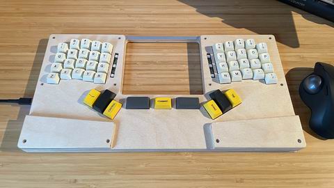
Make a Keyboard
A handwired project and detailed tutorial on how to design and make a keyboard by berkstone.