Keyboard Builders' Digest / Advent Calendar
Declarative keyboard design with Ergogen v4.0
Dénes Bán, the guy who originally created the Absolem keyboard, talks about how it turned into a more all-purpose ergo keyboard generator, and what new features it sports with the fresh release of v4.0.

Published December 20, 2022
Absolem's Afterlife
Some of the more dedicated ergo keyboard aficionados might recall my (now three year old?!) original blog post about building the first Absolem. I shared practically all of my research, thought process, progress, and blunders, all from a still very newcomer-ish perspective, to both encourage others to give this journey a go, and to leave plenty of breadcrumbs to hopefully make their attempts a bit easier. To my delight, a bunch of people seemed interested in my dedication to this "craft", and soon a cool little community started to form over on Discord.
What initially surprised me, but seems obvious in hindsight, though, was how far fewer folks were interested in the Absolem as-is, and how far more of them treated it as just another evolutionary step towards something even more custom. Many resonated with the more aggressive stagger and the thumbfan, but few would have left either unadjusted. Many commented on my necromancing of the pinky angle straight from the '90s, but they would have preferred to apply it to the ring finger also; or use a larger angle; or none at all. Many disliked the one-piece arrangement but appreciated the unique outline, and vice versa.

As the design was mostly generative and parametric already, I found that I could've readily accommodated most of these change requests if I'd wanted to. When I couldn't, though… That stung a bit, as it often uncovered a built-in assumption I hadn't been aware of. I started trying to "generalize away" these assumptions, and since I also wanted to implement PCB-related features anyway, I increasingly gravitated towards a divorce between the Absolem and its generator.
It turned out to be a very good decision, as throughout the next couple of months/years, I gradually realized that the biggest contribution I could offer to the community is not the Absolem itself (as in, yet another "one board to rule them all"), and not even the documentation of how I got to it, but rather its source code morphed into a toolkit to make it easier for people to design their own endgames. This Absolem-based generator generalization is what eventually became Ergogen.
Ergogen 101
I gave an introductory talk about Ergogen recently at a local Open Software Conference:
As there were going to be non-Hungarian talks from neighboring countries anyway, I specifically requested to be able to hold mine in English, so that I can share the video recording from it later on within the international community. I'm very glad I did, as at the conference proper, there were exactly 1, as in one person in the audience during my timeslot, and even he was a colleague staying out of solidarity.

It does provide some consolation that the video seems to be doing a bit better. So if you're brand new to Ergogen, that talk is a good intro. But to make this post as self-contained as I can, let me try and condense the basics into a very quick "what even is this?" overview.
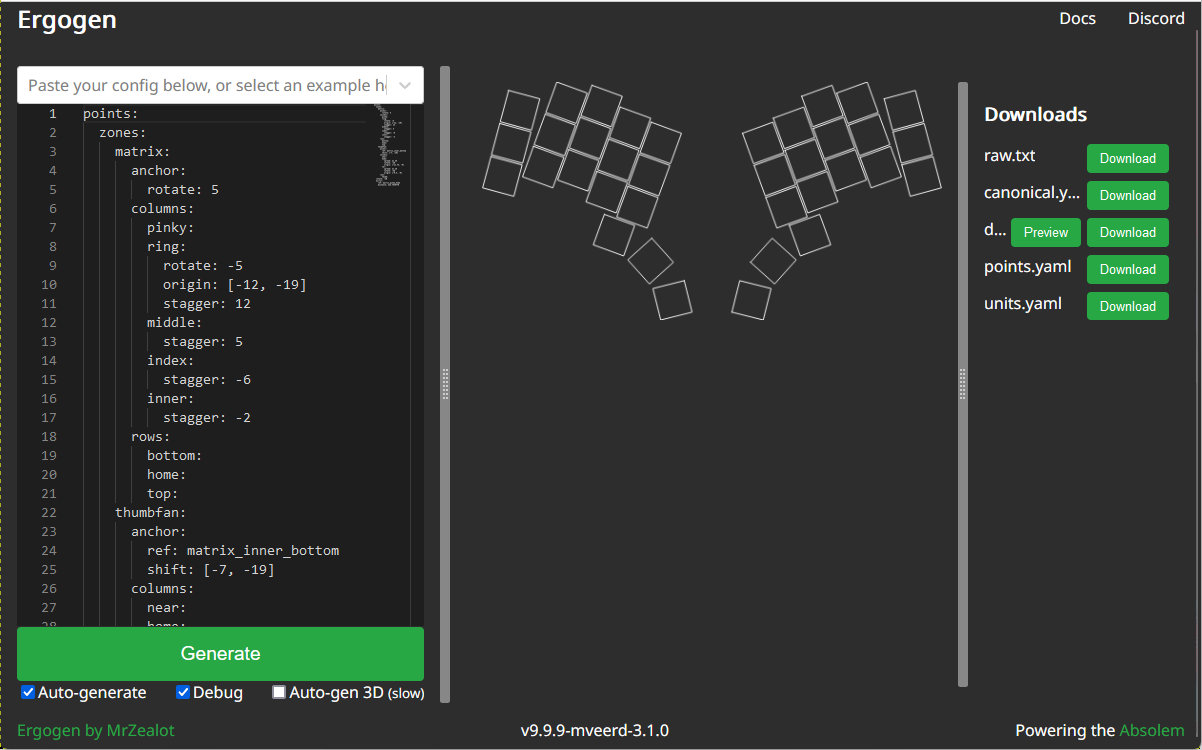
Ergogen is a domain specific language for keyboard declaration. It doesn't have its own syntax, it just piggybacks on JSON/YAML, so it's essentially a config file to tell the generator what to do. The main sections in the config file are points, outlines, cases, and PCBs.
Points help you declare the X/Y/rotation coordinates of the key positions without having to manually calculate everything. It does so by utilizing columns and rows with adjustable spread and padding to lay out a matrix, potentially with per-finger stagger, angles, or other various adjustments. Multiple such matrices are supported through the use of zones, which can be rotated and even automatically mirrored for the other hand to spare you as much work as possible.
Once points are in place, you can use them to generate outlines, meaning anything 2D you can then submit to a lasercutter's. Like taking a large starting rectangle and subtracting a 14 by 14 mm switch hole for each key position. Or merging beveled/rounded rectangles placed at key positions with a polygon center piece to arrive at the Absolem shape. Cases take these outlines even further by extruding them in the Z direction and providing 3D-printable case prototypes.
But the most useful part is probably PCBs. Because if we already have points, why couldn't we put actual KiCAD footprints there instead of simple rectangles? And why couldn't an outline serve as the edge cut of the PCB? Add some global, non-key-related, one-off footprints for MCUs and whatnot, and we have a template that just needs some traces before submitting to the manufacturer.
Hmm, Upgrades…

This already sounds perfect, I hear you all say. Why thank you, but no. There has been (and will be still) a metric shitton of improvement opportunities. I've been brewing on a large batch of these codenamed v4.0 for quite some time now. If I'm breaking compatibility, might as well try and shoehorn in everything I can already see needs its compatibility broken.
Well, I'm happy to report that I finally got around to addressing (almost) everything I intended, and released v4.0 a few days ago. To the critics who preposterously claim that I only finished up because of the fast approaching deadline of this very post, let me just say: you're absolutely right. The winter break helped a lot too, though.
Anyhow, let's get into the meat of what happened this year:
Attribute consolidation
Ergogen has an unapologetic columns-first approach to laying out zones, so specifying key attributes could happen globally, at the zone level, at the column level, at the row level, or at individual key level, in order.
But there were a few attributes (namely, stagger, spread, rotate, and origin) which I initially thought only made sense in a column context.
Stagger makes the columns go up/down, spread moves them left/right, while rotate and origin determine the inter-column angles.
And while it's okay not needing lower-level overrides for these (as per-column setting is as precise as these get), what I didn't consider was that making them column-only values means they can't be uniformly overridden at a higher level either.
The most common example of this was people trying to uniformly set the spread to something other than 19mm for easy choc spacing, which they had to do for each column.
Well, not anymore!
stagger, spread, splay (née rotate, changed to differentiate from anchors), and origin are all joining the rest of the key-level attributes, and will all participate in the same 5-level inheritance hierarchy (global/zone/column/row/key) so that everything can be specified and overridden wherever.
Additionally, individual key adjustments now work cumulatively within a column, similarly to how columns are laid out cumulatively within a zone, so you can now do finger arcs and whatnot, if you so choose. Consistency!
Anchor improvements
Anchors are another, hopefully-more-convenient-than-manually-listing-coordinates kind of way to declare points, either within the points section for permanent, named ones, or during any subsequent outline/PCB layout as temporary helpers. Roughly speaking, anchors work by:
- Optionally referencing one or more already existing starting points with
ref, - Applying some initial rotation with
orient, - Moving the point in that relative direction with
shift, and then - Adding some extra rotation by
rotate.
The main development for anchors in v4.0 is that now they're fully recursive, meaning that refs are no longer restricted to names of existing points, but can be sub-anchors themselves.
This led to an interesting problem, though.
See, when multiple points are referenced within a single anchor, the starting point became their average.
But when the anchor itself was a list of multiple declarations, the elements chained in a kind of follow-the-dots way, each anchor in the list becoming the starting point for the next.
So what happens if a now fully recursive ref attribute is a list?
Is it a list of things to average, or is it a chain to follow?
The solution I chose was to separate out a new field called aggregate, which contains sub-keys parts, method, and potentially any other method-specific extra fields in the future.
For now, it's only for the same averaging behavior we've had so far, so method=average by default, and parts is the array where each element is parsed as a separate anchor and then averaged.
Possible extra methods like min, max, or, say, linear interpolation with a parametric coefficient are easily doable later.

Also, I did even more trigonometry, so you have to do even less trigonometry.
Meaning: recursivization applies to orient and rotate as well.
If they're numbers, they work the same way they have, but if they're anything else, Ergogen now attempts to parse them as sub-anchors, and "turn towards them".
Arctangents for the win.
What? Where?
The points section started with the implicit assumption that all of them would be treated equally down the line. Later, a simple tagging feature was patched in when I realized that being able to isolate certain subsets would be beneficial – like, say, laying out different switch footprints at different locations on a choc+mx combination board because choc and mx are not spaced equally.
But then this tagging (or shall we say, "filtering") got me thinking: why is there a keys outline type that puts rectangles at switch positions (potentially filtered by tags) when there's an additional rectangle type that just puts one somewhere.
Also, why do we have to declare what kinds of footprints we'll want later for a point in the points section when subsets could be selected and footprint-ified within the PCB section (where it would more logically belong)?
Some refactoring was in order.
Scrapping tags, I implemented a generic filtering system that can select points by defining conditions on any piece of metadata, through equality check or even regular expressions, combined with arbitrary and/or aggregation.
This led to a where clause that can be A) such a filter to use a subset of existing points, or B) an anchor to declare a temporary helper.
And once I had where, the thing I wanted to put at those positions (shapes in the case of outlines, and footprints in the case of PCBs) just had to change their names to what for thematic bliss.
This way, the points section can remain dry, outlines have been de-duplicated, and PCB footprints are defined where they should be. Win-win-win.
Outlining overhaul
Many people had negative experiences with gluing and binding. In Ergogen parlance, glue used to be a dynamically resizing connection element that could hold the two sides of a board together, while binding is like an extra, directional outgrowth around each key position to make sure that they can "reach their neighbors" and form a cohesive unit when combined.
As you can probably guess from the tense usage in the above explanation, glue is gone.
It was just there to provide "resizeable polygons" that could shrink/grow with the size of the keys layout – but since it was confusing, rarely used, and it's already possible to substitute this functionality with preprocessor variables, it lost its purpose.
If you never knew what it was: you're safe now.
If you did: you're welcome.
Binding, on the other hand, will remain a key player.
But good news: there's now an auto-bind feature that's gonna be able to satisfy 99% of common use-cases without user blundering incompetence inconvenience.
It's within-zone only, checks the columns in declaration order, and applies automatic bind values where they're manually undefined.
Up/down is based on how a point's y value relates to the column's min/max y bounds, and left/right is based on whether the point's y value is within the previous/next column's y bounds.
This leads to a nice effect along the lines of "if there's something in that direction already, might as well reach out towards it and connect up".
Additionally, filleting, expanding and scaleing moved from the outline reference type to be generic to all shapes, meaning you can do these operations at any stage during the part combination process, even for rectangles or polygons.
Plus a new generic adjust anchor field has been added so you can, well, adjust the positions of outline elements uniformly.
For example, you can now lay out stuff below each key, not only at each key.
Footprint sideloading
As I've said before: the 400+ stars on GitHub are the reward for past me doing arguably good work, while the almost 200 forks are the punishment for present me still not having done footprint sideloading so that everyone can just use the official repo without needing homebrew mods.

The new release brings the ability to specify folders as the main input instead of a single json/yaml file.
If so, the folder must contain a config.yaml doing the actual heavy lifting, but the point is that it can also contain other stuff.
For now, this "other stuff" is just ergogen-ized javascript footprint files in a footprints subfolder, but it can later extend to SVG/DXF files for outline imports and PCB silks, 3D models for case construction, etc.
What's more, the input can be a similarly structured ZIP archive as well, with the extension left as .zip or changed to .ekb for "Ergogen KeyBoard".
I'm hoping this will dramatically reduce the need for people to fork the project, as they'll just be able to use custom footprints alongside standard config files in standalone bundles going forward.
The WebUI doesn't yet have a way to accept packages, but the command line version is ready for action.
Footprint improvements
Until now, footprints made it the user's problem to know which of its parameters are nets, which are anchors, and which are just raw values.
To make the situation easier, footprint parameters are now flattened under a single params key, leaving type checking and metadata handling to the footprint authors – of which there might be many more soon thanks to the above-mentioned sideloading!
Footprints also inspired the creation of "mirroring resistance".
It's when an anchor refuses the special treatment of negated x axis movement and clockwise-to-counterclockwise rotation conversion on mirrored reference points.
This special treatment is necessary so that mirroring the left hand side of the keyboard should still leave things at the right place on the right side – but for footprints that get printed on the same side of the PCB, it could cause problems users needed to manually play around.
With the new resist attribute of anchors, this became parametric.
Along with this, the internal footprint API now supports separate placement functions for internal/external and symmetric/asymmetric coordinate calculation.
Lastly, replacing the old redirection strings starting with an equal sign, footprint parameters can now fully access (and even combine) key-level metadata through template strings using familiar double curly brace syntax (like {{field}}_{{nested.field}}).
What's Next?
You think all this means we're done?

Here's what I have planned for the future:
- First and foremost, I'm instating a strict feature freeze until there's complete and up-to-date documentation. And complete not in just the sense that every feature is at least mentioned (which would be the bare minimum), but also in the sense that there are sufficient examples, pictures, guides, tutorials, whatever. It's both a blessing and a curse to finally have a project that others seem to be interested in…
- Make the official switch to a better web interface. If anyone happens to be unaware, there's ergogen.xyz which I hacked together, and then there's ergogen.cache.works that's – shall we say, a bit more usable and elegant, contributed by the awesome ErgoGeneral Cache. As soon as it's ready to accept the v4.0 engine seamlessly, it will replace the current deployment as the default GUI.
- Getting to 100% test coverage – which is not going to be as hard as it sounds, fortunately, as we're already at around 95%, I might add. But either way, it was always a goal to make something that's both worth testing and is tested properly, so here's my chance.
- Then it's gonna be on to v5, which will be all about footprint API standardization, onnx-style incremental update-ability, and automatic kicad-to-ergogen footprint interpretation.
- Then on to v6, which will be about fleshing out the current 3D support skeleton crew for fuller, more integrated case generation capabilities.
This is as far as I see now – which is just as well, as this is quite the ambitious vision already. For the moment, though, v4.0 is here! And even this post about v4.0 is here, as you can attest. I can rest for Christmas with a clean conscience.

In conclusion: if creating your own keyboard sounds like something you'd be interested in, but going about it from scratch seems a bit daunting, give Ergogen a go and see where it leads you. And if you get stuck anywhere along the way, I'm sure the kind folks over at the Absolem Club discord will be happy to nudge you in the right direction.
 | Dénes Bán (33)mrzealot |
|---|---|
| Location | Szeged, Hungary |
| Description | Ergo keyboard evangelist and tool creator |
| Occupation | researcher, developer |
| Joined | 2018 |
| Niche | monoblock splits, generated boards |
| Fav. switch | Variable weight Chocs |
| Fav. keycap profile | MBK |
| Other hobbies | reading, blogging, procrastinating |
| Links | https://zealot.hu, https://ergogen.xyz, https://preprocessor.blog |
Published on Tue 20th Dec 2022. Featured in KBD #108.
Related

Spleeb
An open-source split by Christopher Hoage loosely based on the Ergodash: Spleeb.
Mantis v0.2
Felix Kuehling's Mantis v0.2, sporting HEX keycaps, has now PCBs on two levels to imitate tenting.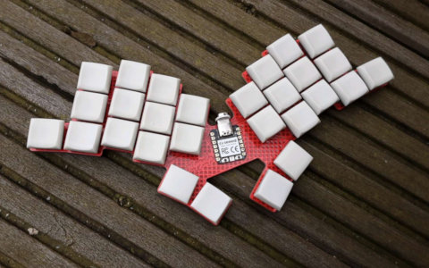
Zilpzalp
Zilpzalp is a 28-key monoblock split by apfel, designed via Ergogen and featuring a XIAO controller.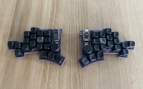
Wysteria
Wysteria is jwe's split keyboard with lots of features.