Keyboard Builders' Digest / Tips & Tricks
From switchbody to 3D keywell
Chris Trotter's Fusion360 tutorial details how to design custom parametric keywells, used e.g. for his ArcBoard.

Published December 17, 2023
The goal of this tutorial (available as a google doc as well) is to take someone sort of familiar with Fusion360 and give them steps for creating a parametric 3D keywell. If you know how to do basic sketching and modeling, this doc should be enough. I’ll provide a list of supplementary resources.
Disclaimer: My day job is not in CAD, I have no formal training, and only two years’ experience, but… I did sleep at a Best Western last night.
What you can do with this
Most generators can’t do per-column pitch/yaw adjustments. This method gets you effectively unlimited configurability without being a hot mess to manage.
However, the curviness of the board is greatly lessened when using more than four keys in a column - cuz geometry.
The method can be extended to the pcb retention plate…
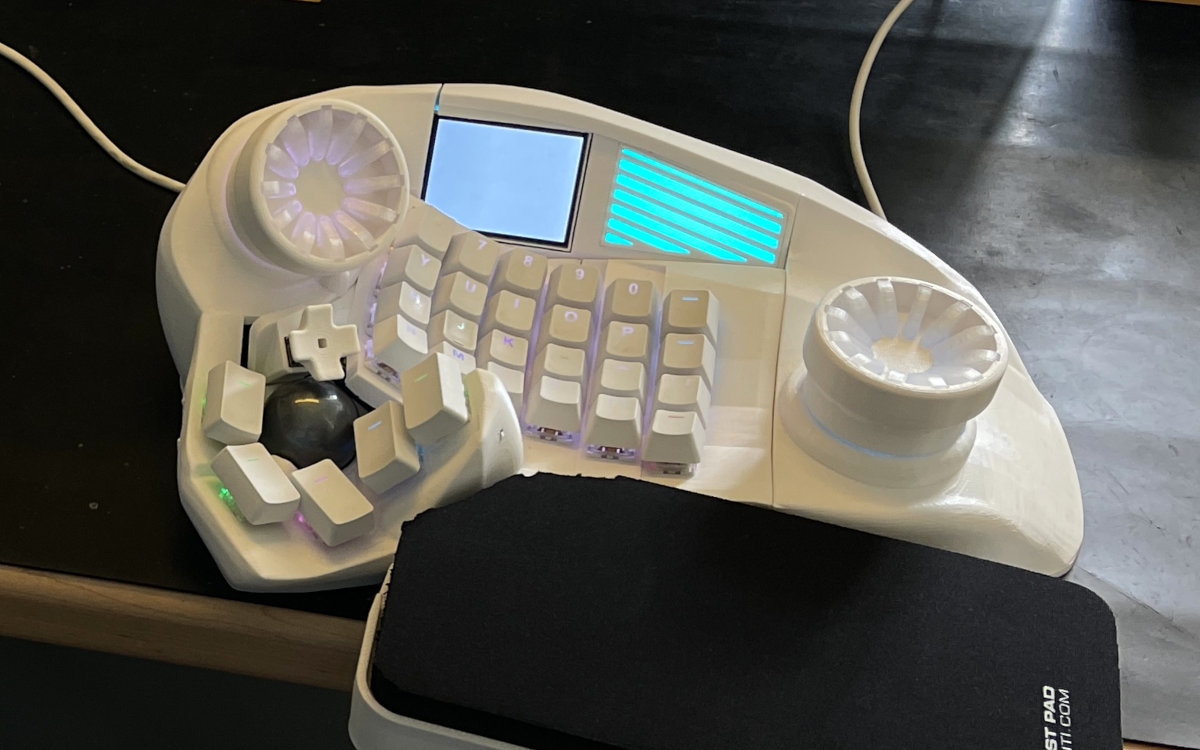
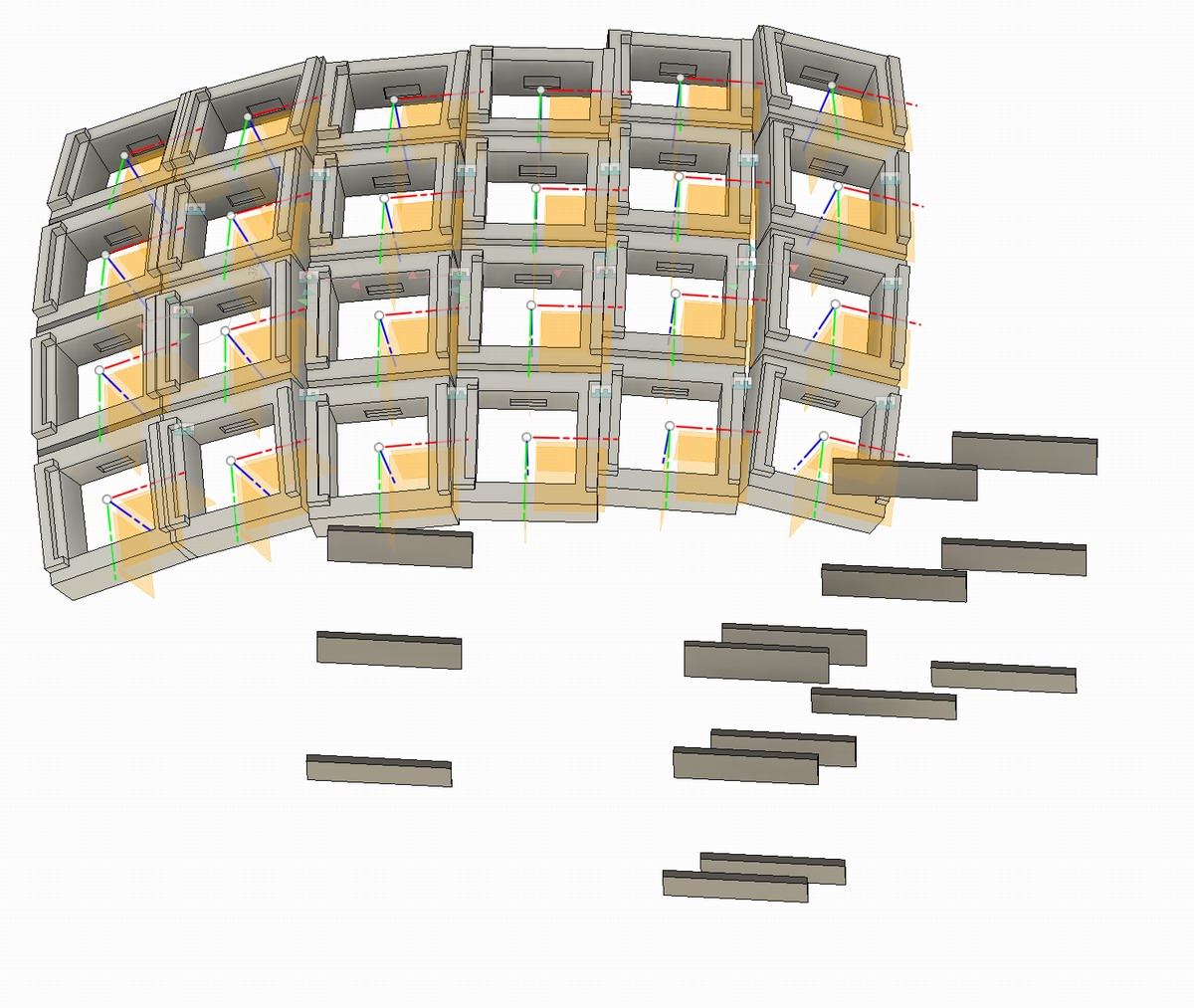
Here’s an example of what using this method looks like, practically.

We have:
- two column modules
- ball joint holding them together
- rigid group holding it all together
- sketch of each column side profile
- equal loft, single action, to join the two profiles
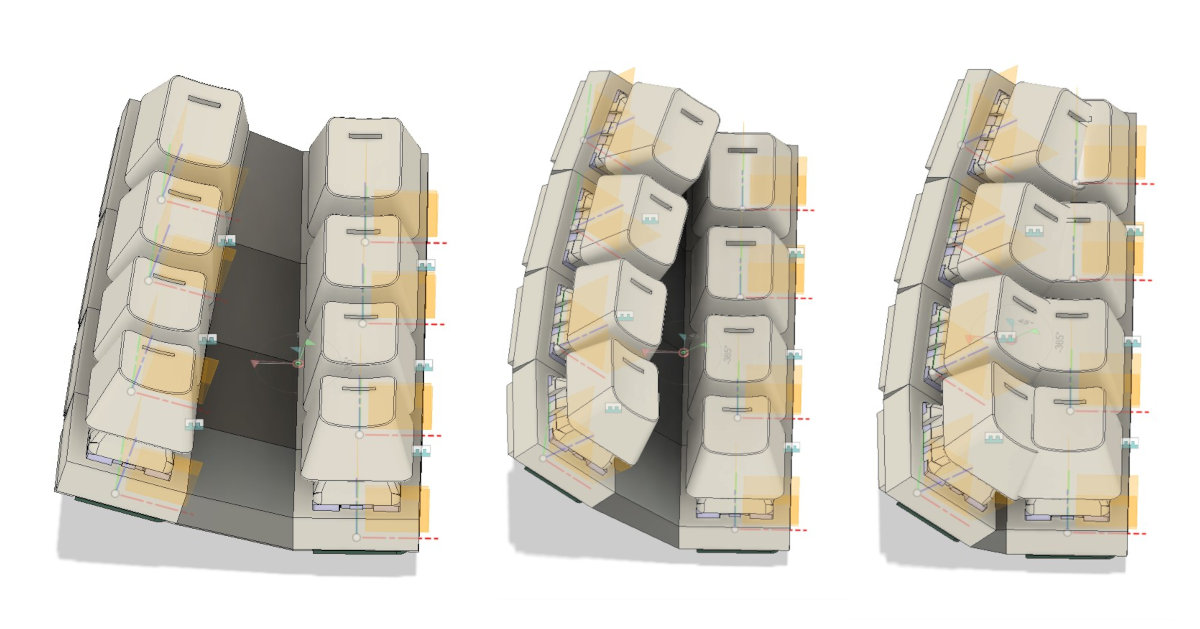
- Adjust separation to be much wider: 5mm -> 15mm.
- Adjust yaw angle to be much wider: 15deg to 45deg.
- Now bring separation in: 15 to 1mm.
- Bringing the cols even closer:

Components
Components I’m using:
- Cyboard.digital Dactyl Flex PCB system
- Note: even with the press-fit method I show here, you still need a way to mechanically retain the pcbs.
- Note: while the pcbs are remarkably flexible, they introduce a design constraint - you have to keep them in a straight line (as pictured throughout this doc).
- standard MX switches + keycaps
- no Choc at this time; maybe in future - but this is a relatively easy thing to change up in the parameters. However, the Cyboard pcb is MX-only.
- PETG filament (has some flex to it; PLA tends to snap)
- M3 hot-melt inserts (I prefer CNCkitchen)
Notes on the design process
What I lay out here is just what made sense to me - both from external input (amazing discord folks, youtube videos, Quentin@BKB-said) and my own experience.
So don’t take what I’ve done here as ‘the way’. It’s just ‘a way’. O-kay?
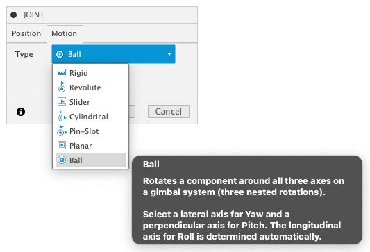
Notes on joints
Two types of joints are used. Joints are a Fusion360 concept for locking components together in various ways. We’ll be using ‘rigid group’ and ‘joint - ball’.

Layout
There will be three designs (i.e. files) used here.
- switchbody: a single body that provides a way for you to ‘plug’ in the pcb and mx switch
- column: a collection of switchbody components with any gaps filled in
- keywell: a collection of column components with any gaps filled in
The component inheritance looks like this:
switchbody -> column (group of switchbodies) -> keywell (group of columns)
Switchbody

Column
Keywell
Some critical parts of each component model:
- everything must be jointed or locked together with a ‘rigid group’, else you will have disasters when moving things around
- don’t be ‘me-for-the-last-two-years’, name all your bits and pieces
- external components get their own internal component, e.g.:

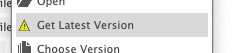
- any significant change to an ‘upstream’ component should be seen as an opportunity to go ‘downstream’ and ‘get latest version’ of the inherited component, e.g.:
- naming helps your brain - name things with names that make sense to you!
Design
The switchbody

Order of operations:
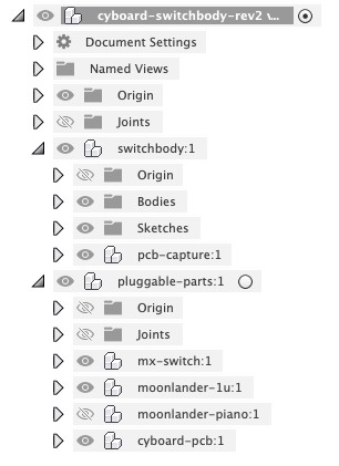
- create your component tree: CRUCIAL to put all of your external components in a component separate from the switchbody – this helps you down the line when you have to hide these pieces prior to printing. E.g. “pluggable-parts” is what you can see in above example screenshots.
- sketch the top of the switchbody; extrude to size
- sketch the mx spring-tab cutouts; extrude to size, mirror
- add your external component for the pcb
- sketch the pcb-capture features; extrude to size
- add your external components (mx switch, keycap(s))
- create any joints/rigid groups
Create your component tree:
- switchbody
- pcb-capture
- pluggable-parts
- mx-switch
- 1u-keycap
- cyboard-pcb
Sketch the top of the switchbody.
The dimensions here are up to you (component choices) and what your printer can do (some print a bit too small, or too large).
I have been using 20mm center-to-center key cap spacing.
13.9 mm MX switch size is what works for me.
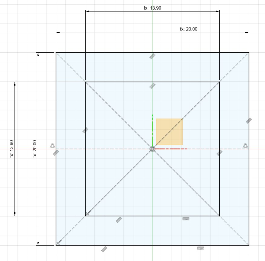
Note: Parameters are super useful, but without fully-constrained sketches, you lose out.
I put some examples of how I use parameters (see below) - but I’m definitely not an expert here.


A good rule of thumb for parameters is if you are entering the same dimension number over and over…it should probably be a parameter.
Sketch the mx spring-tab cutouts.
If you look at the side of an mx switch, it’s obvious how this feature functions - just a space for the spring-tabs to ‘spring into’.

Sketch the pcb-capture features.
This is entirely dependent on pcbs, but the measurements I use are seen here.

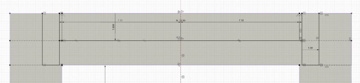
How the pcb-capture works is best illustrated here:
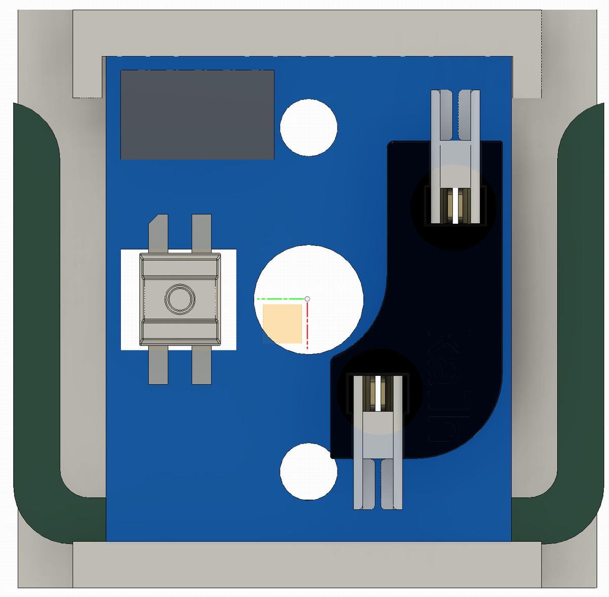
- At the top of this picture, there are locators to keep it on the right mx switch center
- At the bottom, another locator to provide ‘press fit’ functionality
There is a slight taper here (red boxes), this helps keep the pcb held in place. Though, not enough for all hotswap operations! (the pcb clamp part is not part of this doc)

Btw, if you’re wondering how I got this view:
- type ‘s’
- type in ‘sectional analysis’
- you’re welcome
Create any joints you need, e.g. the final ‘rigid group’ joint.

Save the design. I’m not good at using the description fields/milestones, there is probably a good reason for doing this periodically.
Print it out. Now. Oh, it’s not quite right? Perfect, adjust the sketch and print again!
Still not right? Well, good thing you didn’t print the whole keywell and discover this like I did. Right?
The column

This component is really not much more than…
- your switchbodies laid out with the angles you want
- lofts to fill the gaps
- rigid group to hold it all together
Note: My experience with joints is to use the same order when selecting edges.
- e.g. component1: side, then top -> component2: matching side, then top
- doing it out of order causes you to have to enter negative values and it gets mentally confusing.
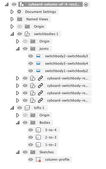
Create your component tree: switchbodies, lofts

Insert your first two switchbody components in.
- Select your ‘switchbodies’ component.
- In the left project pane, right-click your switchbody design.
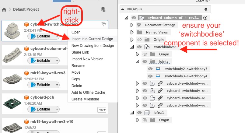
Insert the first switchbody.
Leave it where it lands (at the origin) - this will be handy for future design points.
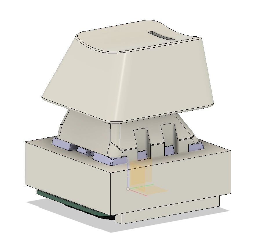
The origin is the xyz coordinates of 0,0,0 - looks like this:

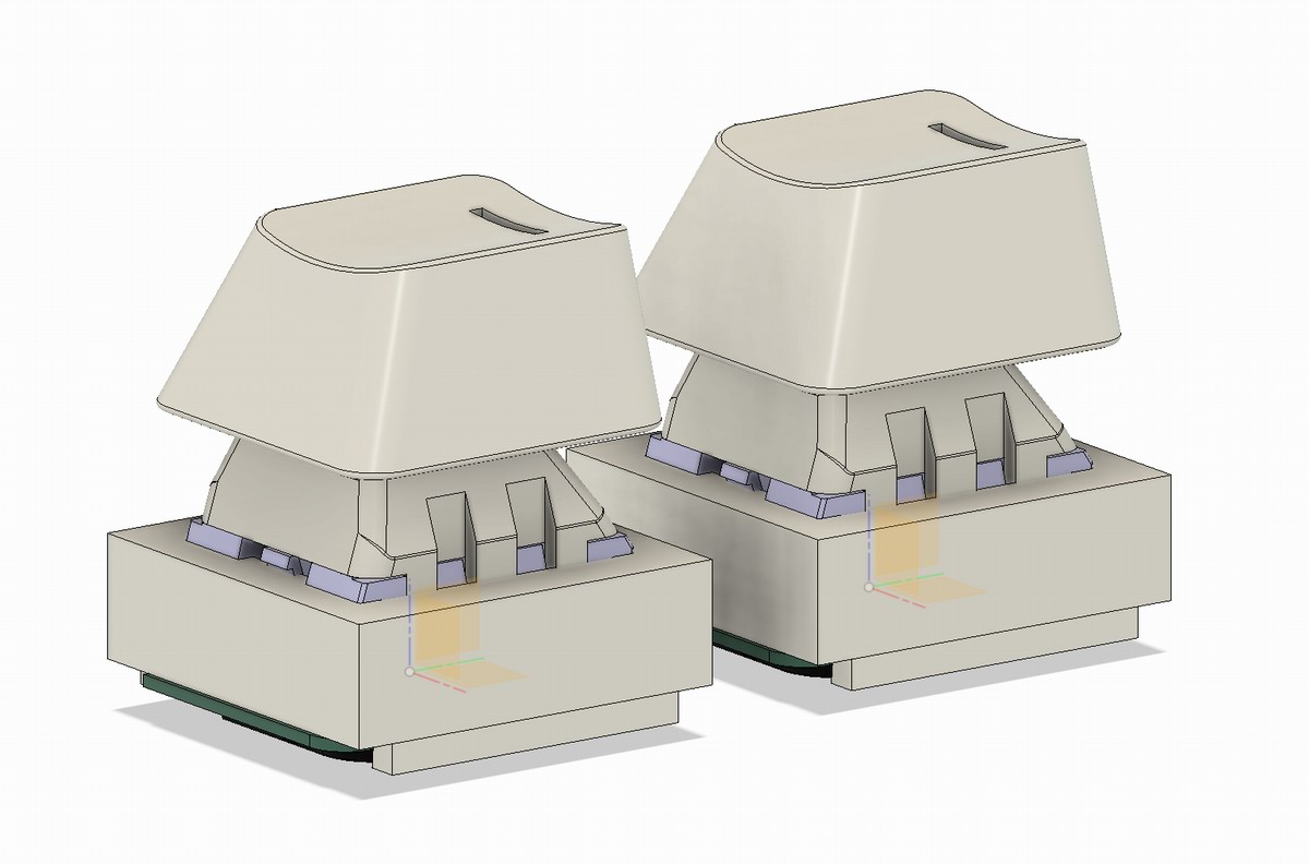
Insert the second switchbody, move it out of the way - makes your life easier.
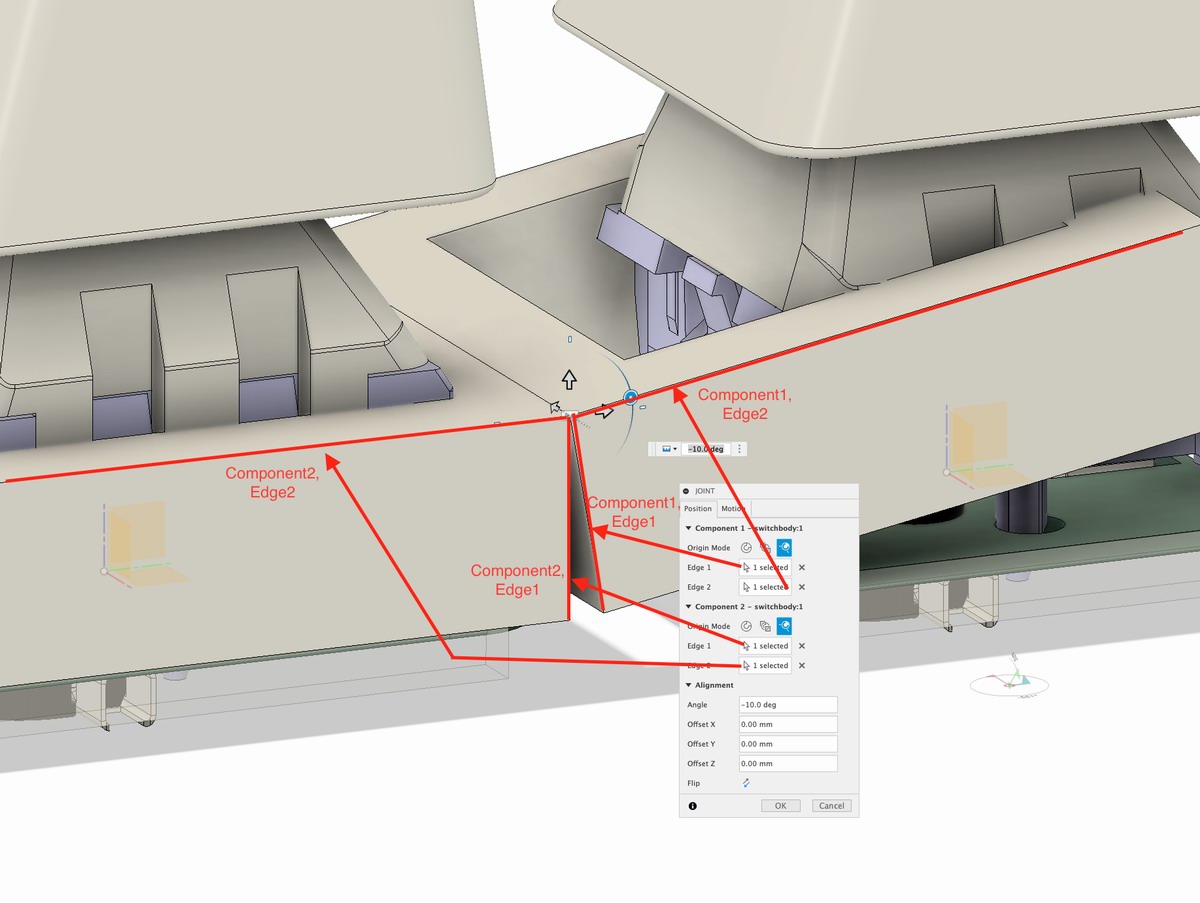
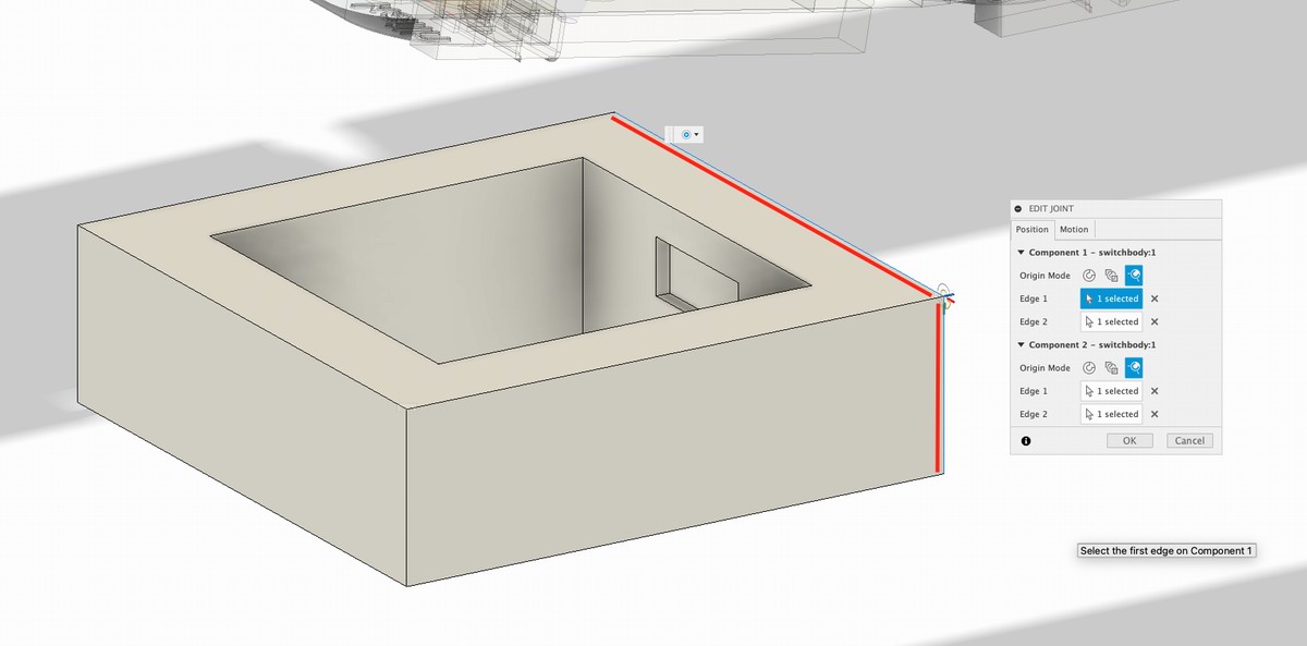
Type ‘j’ for your first joint.
- I found it easiest to do ‘two edge intersection’.
- See it as, “we are moving component1 over to component2”; this is how jointing just seems to work.
- See diagram to explain best which lines to choose.
- I use 10-degrees, you do you.

TIP: Click and hold to get a list of things to pick! Helpful when there are a lot of overlapping things.
Repeat that process for as many switchbodies as you have in your column.
The red arrow indicates the ‘origin’ switchbody.

Select the profiles of each switchbody (‘p’ key while sketching).

Draw a line between each bottom gap to make a triangle.

Extrude those triangles to a point - the other side of the switchbody.

Rename yo stuff.
Done! Don’t forget the rigid group process…!!

Otherwise you get this…
The keywell
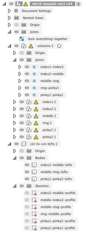
Create your component tree.
- tracing-aid
- columns
- index1
- index2
- middle
- ring
- pinky1
- pinky2
- col-to-col-lofts

Use the ‘tracing-aid’ like this:
- in fresh design file, insert mesh -> whatever keyboard STL you want.
- make sure it’s lined up to origin properly (e.g. sometimes they import in sideways/vertical)
- now you can visible/hide (‘v’ key) the tracing aid as needed to line up your custom columns
I lined up my first column against my tracing aid. I am sure there is a better way of doing this.

Ok, complicated part again.
Do a joint - the closer to the middle, the better - between a switchbody from Col2 and a switchbody in Col1. I used the ‘origin’ switchbody.
You need to use the other axis here.
Same deal, mirror the same edges you picked for component2.
TIP: Click and hold to get a list of things to pick! Helpful when there are a lot of overlapping things.
But, this time, we don’t want a rigid joint, but a ball joint.

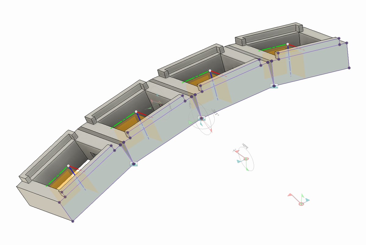
Offset X, for example, allows you to space out the columns.

And, we want to pick custom axes for Pitch and Yaw.

The Pitch axis line. (It’ll be the other switchbody for you - my test joint was done backwards, I believe.)
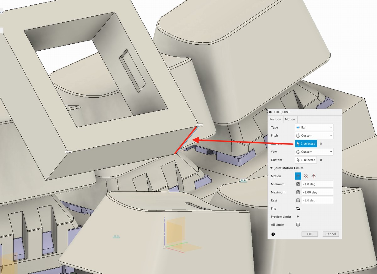
The Yaw axis line. (It’ll be the other switchbody for you - my test joint was done backwards, I believe.)

Now, you can adjust pitch to suit.
BUT. Keep the min/max to the same value. This locks everything in place.
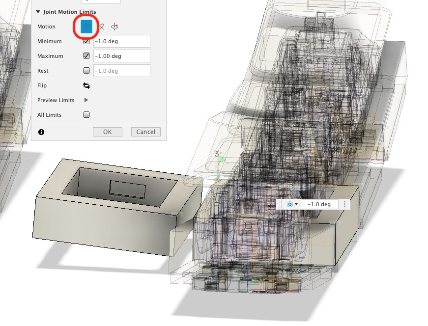
And, yaw - same caveat applies.
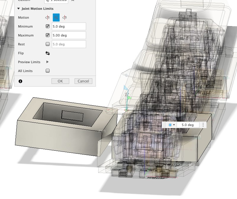
Voila.
Rinse and repeat for the rest of your columns.


You want to ‘daisy chain’ them. Adjusting one column has downstream effects.
Try experimenting with other methods!
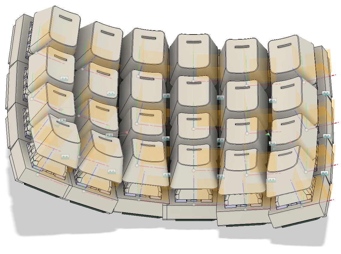
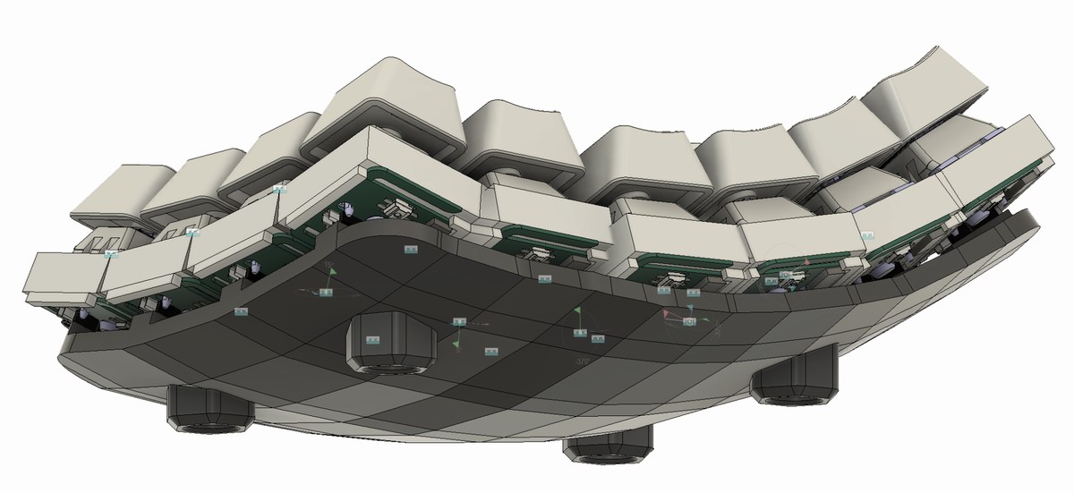
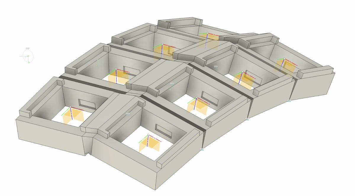
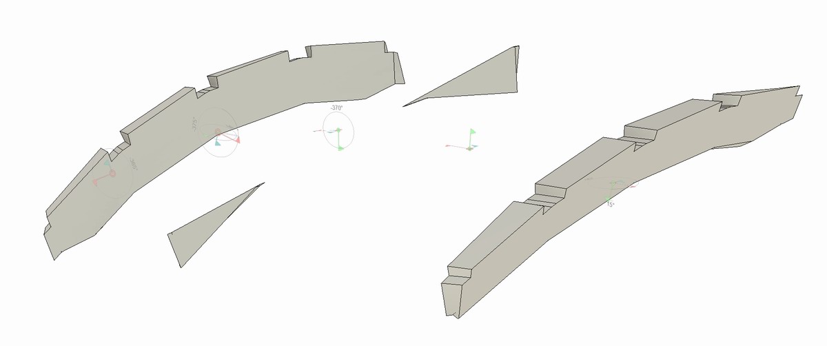
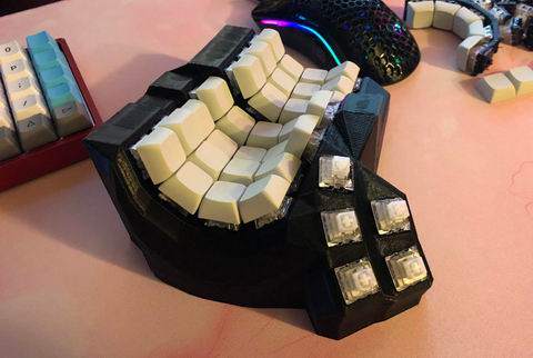
What mine looks like fully assembled:
I would note there are ergonomic reasons to NOT have the ring/pinky columns curve upwards like this. I will probably experiment with that in future. For now, it’s what I’ve been using so far.

Also, this method means you can easily experiment with different keywells.
I’d also note once again that this is really only useful if you need a 3D keywell. The online generators do a pretty amazing job for most use cases – just not custom 3D keywells.
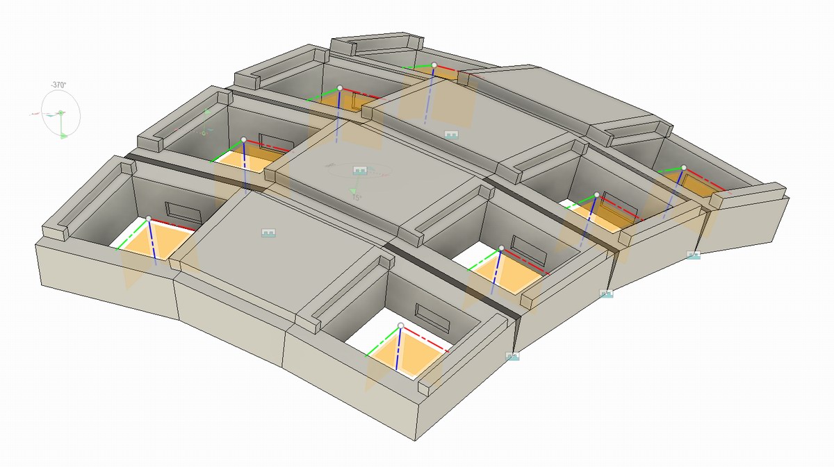
Keywell lofts
There will be gaps - even with the tightest possible spacing. So we need to fill in these gaps.

Profile sketch, including pcb captures, each side of the first gap.

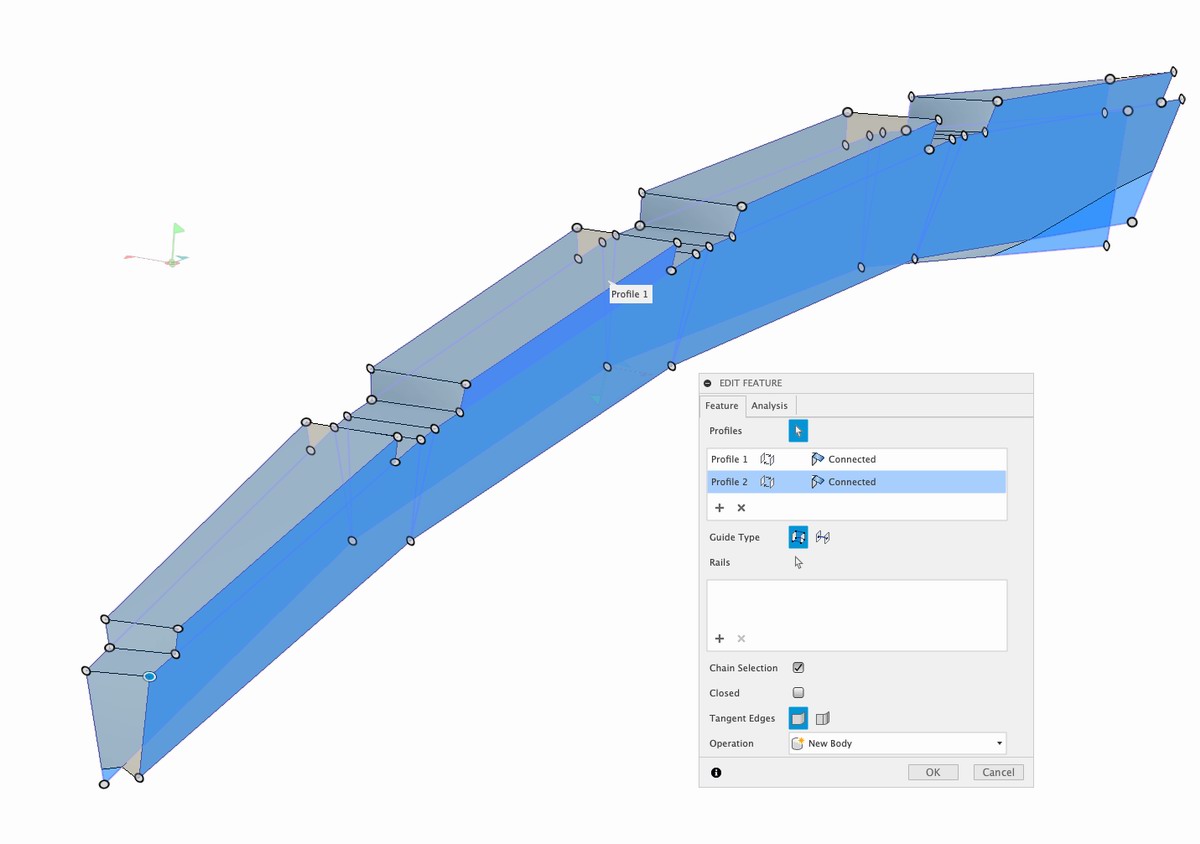
Now, loft the two together.
- select every profile on one side, sequentially, as in, each profile must touch the next one!
- this will get you everything in one sketch on one loft profile
- do the same for the second sketch
- don’t worry if it throws errors halfway through selecting the second sketch, if you haven’t made any mistakes, it’s just the lofting tool struggling to keep up. finish the selection and it’ll work out fine.
To illustrate how this works…I changed the ball joint Offset X for this pair of columns from 1.5mm to 15.0mm.
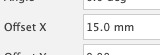
Boom.
If your spacing is too tight, you might get lofting collisions. No worries! Just…
- adjust the ball joint to be very spaced out
- create the loft
- adjust the ball joint to be what you want
- and… it’ll shrink the loft appropriately, no fuss!
There we have it. Your very own 3D keywell.

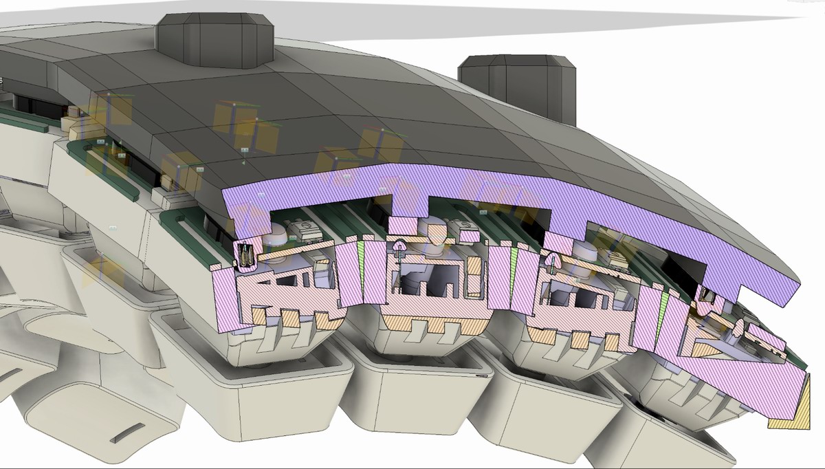
PCB retention component example
The Cyboard pcbs will pop out occasionally when you are installing switches, so, Cyboard’s keyboads come with a retention component.
This was my take on how to solve that problem… (not printed yet)

Fusion360 protips
- Use the ‘s’ keyboard shortcut! Just learn it, saves a huge amount of time/mousing around.
- Learn sketching constraints, master them - you will save a huge amount of grief in the long run. I’ve probably wasted literal months due to being ignorant of this/procrastinating learning.
- Parameters only make sense when all of your drawings are fully constrained (red lock icon).
- Component inheritance and component layout makes life easy.
- Learn to use the timeline!! E.g. “oh, I missed a chamfer, let me run another chamfer operation” -> go back to the chamfer operation in the timeline, add to/update it.
- Correct any errors immediately, or risk sadness.
- Step files are your friend - electronic components and the like can usually be sourced off the internet for free as Step files (.STEP), and they import into Fusion as an entire model.

General experience protips
- Get a cheap digital caliper (mine was $10) and a 6” scale that has millimeters, makes dialing in your sketch-to-print much easier and faster.
- Buying a Prusa MK3S definitely saved me a ton of time and grief - though there is still a lot of basic maintenance know-how that requires a learning curve.
- Printing gives off particulate – a lot of it – an enclosure w. fan/filter saves you cleanup and lung problems.
- Acetone for the print bed cleaning (see manufacturer’s requirements before blindly following this).
- Expect to go through nozzles – I’ve not had good luck with cleaning methodologies. Over two years of printing, probably 5-10 nozzles junked.
- Design your part with a specific print orientation in mind. E.g. pcb capture (press fit features) dimensions change if there is support material involved - ensure you design for the specs you expect to print in - then only print that way!!
- Be ready for failure. Be intentional about the learning. I’ve found a journal to be a very helpful discipline tool. E.g. Use the slicer’s ‘cut’ tooling so you are printing out only a fraction of the entire part – prove out theories cheaply!
Would you like to know more?
If you are in that small minority who want a 3D keyboard that can’t be made with the current crop of generators, well… you need: to learn a CAD tool (e.g. Fusion 360), you need a 3D printer, basic soldering iron, and lots of parts.
A great starting place would be to get any QMK-compatible keyboard and learn the firmware. Rather, start with the docs: https://docs.qmk.fm/
However, if you’ve read this far…well, frankly, just order a Prusa, sign up for Fusion 360 community edition, and start designing and building.
One big note: a printed board with switches/caps is a totally different beast from one that is fully wired up and flashed. So try to be intelligent as possible with your experiments before committing to a full build.
Discord
- fingerpunch
- QMK
- BastardKB (#3d-design)
- Cyboard
- MechKeys (#kb-ergo)
YouTube learnings
- Sketching: here, here, here, here, here and here.
- General Fusion stuff: here, here, here, here.
- Parameters
- Fusion Forms playlist
- BastardKB has some great live-stream type videos on design. This was the entry point for me! Thanks, Quentin!!!!
If you’re interested in reading the journey of someone with zero knowledge to ‘writing this doc’, my build journal is here.
FAQ
What’s the difference between this and something super amazing like Cosmos?
Good question. 99.99% of keyboard builders will never ever need what I’ve written up here. If you fall into that tiny minority, ball-jointed columns is game-changer stuff. But some details:
- You can adjust per-column…
- xyz angles (the generators get you two axes, and that is applied across the range of columns)
- xyz offset (generators also get you this, but not per-column)
- You get a keywell component to drop into whatever other fancy 3D keyboard you’re working on.
- The cosmos-beta does export step files (how cool is that?), but your key components are just floating in space, so you still have a lot of lofting and pain ahead of you if you need to pull them out.
- The component is easily re-used!
- Generators are generally hand-wire only - this method allows you to use whatever pcb you want. (per-key, flex, line-driven solar fusion, etc)
- Read: RGB RGB RGB
Why would you want to spend so much time on this? Just buy a Charybdis or Imprint or whatever!
If your needs are not met by whatever is available, all you can do is DIY!
But seriously, this is way too much work…
If you have medical issues and a keyboard can help…would you not try? I did! Hopefully this helps others out there.
But surely someone is already manufacturing something like this…
A few folks come close. In my case, the KeyMouse Track was the closest - unfortunately it’s closed-source and still seems to be in beta testing. And anyways, I couldn’t use that trackball layout. So…I made my own! It’s helped me keep working for over a year now.

| Chris Trotter |
|---|---|
| Handle | crazymittens |
| Location | Oshawa, Toronto |
| Description | Building boards to help me keep working |
| Occupation | making things better |
| Joined (the hobby) | 2022 |
| Niche | Maximum resting comfort and pain reduction |
| Links | blog.practicaltech.ca |
Published on Sun 17th Dec 2023. Featured in KBD #2023.
Related
Dactyl Manu-tide
Smeeba posted Kravchenko32's Dactyl Manu-tide featuring an extreme keywell (git).
The early days of Keykrush ORCA
Veronica of Keykrush talks about the development journey of the ORCA – an exciting wireless ergo split keyboard in the fundraising phase.
Trackswitch Manuform
Rishikesh Vaishnav's Trackswitch Manuform introduces a mouse-level shift mechanism.
Wizergo
Wizergo by 70rch – A handwired ergo split keyboard with keywell, encoders and GX16 aviator connectors between the halves.