Keyboard Builders' Digest / Tips & Tricks
Improved square matrix
The improved square matrix is actually a round-robin matrix handling the same number of switches – but with less diodes.

Published May 9, 2022
As a follow-up and short supplemental material to the square or round-robin matrix featured last week, let me introduce a little upgrade: the improved square matrix.
The improved square matrix is almost the same as the "traditional" round-robin matrix but achieves handling the same number of keys with less diodes. Possibly, by one extra diode per pin rather than an additional diode per each switch.
As usual, the suggestion came from Ikejima (thanks!), and this all depends on the electric characteristics of your diodes, controller, etc. – thus, may require some measurements, calculations and proper planning on your part.
If you haven't read the original round-robin matrix piece yet, check it out before continuing with this write-up. All the details and logic are explained there, as well as the concept behind matrices utilizing the voltage drop across diodes to eliminate ghosting.
This time, let's begin the discussion where we've finished the story last week.
With the schematics of a 3-pin "traditional" round-robin matrix – connecting the pins with switches in every possible way:
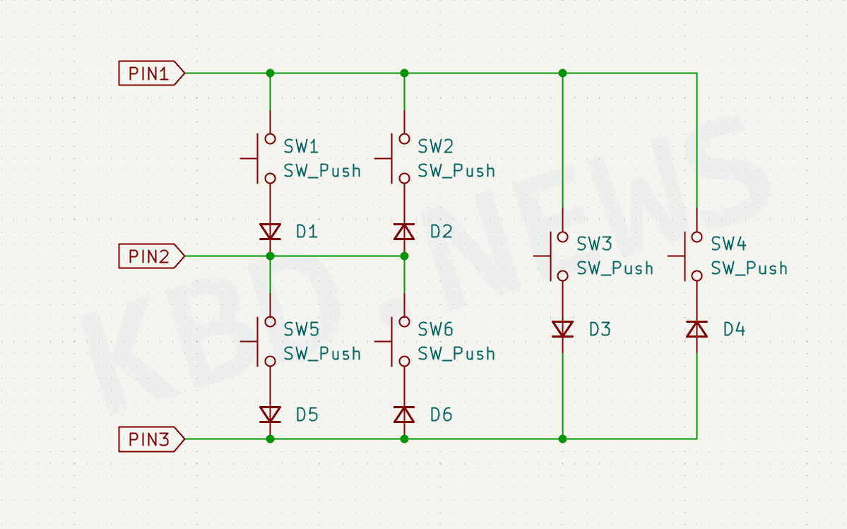
As already told, this arrangement could cause ghosting without proper planning. By pressing only two keys, the controller/firmware can register another (unpressed) one as a keypress.
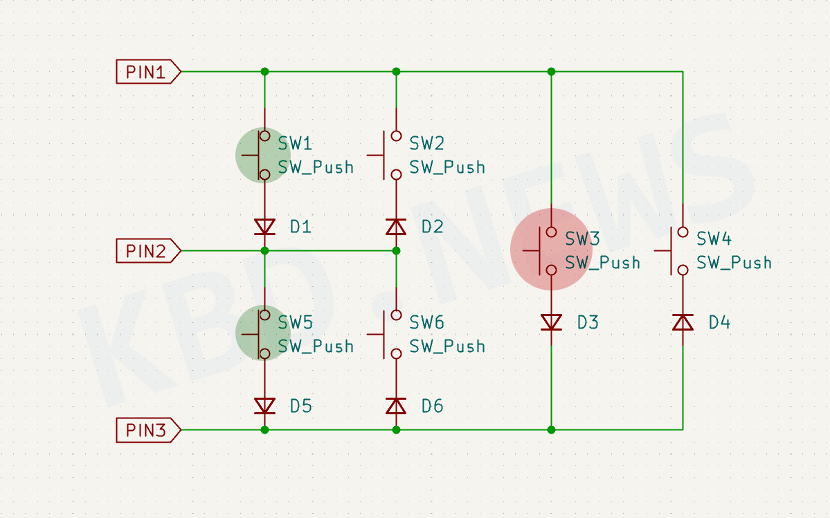
This means, for this matrix to work properly, you have to ensure the cumulative voltage drop across only two diodes will ensure the signal gets weak enough to prevent a state change of the GPIO pin.
In fact, in some cases, you had to utilize two diodes per switch.
Double diodes
You can choose diodes with higher forward voltage, but if you only have the most common 1N4148 ones (about 0.7V), you have to use two of them for each switch.
By using two diodes per switch, we are pretty safe: that's 2x2=4 diodes along the ghost path so 4x0.7=2.8V. There's no way that's registered as HIGH e.g. with an RP2040 and PULLUP.
But two diodes per key? There must be a better way. To prepare the solution, let's rearrange the schematics. The two frames are the same. Actually, the new one is Ikeji's original arrangement. Don't forget, the diode symbol most likely represents two diodes!
Improvement
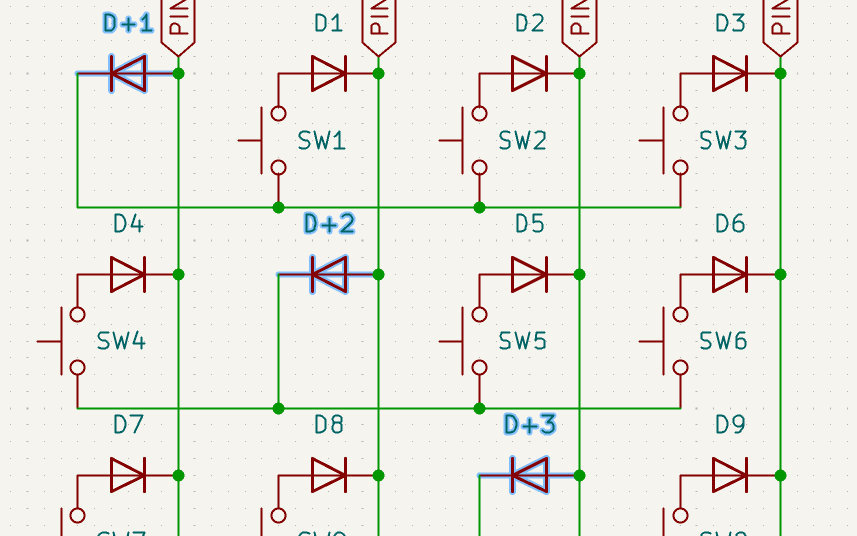
And here is the improved square matrix. With one extra diode per pin you (most likely) don't have to use two diodes per switch:
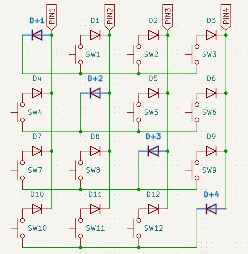
If we count with 1.5V threshold voltage, the traditional square matrix required voltage drop between 0.75V and 1.5V which is probably higher than your 1N4148 diodes' drop.
However – and this is the novelty of the improved square matrix –, by introducing an extra diode per pin (not per switch!), we force the signal to pass through three diodes. (Actually, it's rather four diodes. I can't find a 3-diode path but let me know if you spot one.)
(So we get back to a similar situation what we've seen with the (Japanese) duplex matrix – a previous 3-diode path.)
By using the improved square matrix the required voltage drop per diode is between 0.5V and 0.75V, and you can just use the 1N4148.
How to calculate the required forward voltage?
As always with these exotic matrices (at least the ones utilizing the voltage drop across diodes to eliminate ghosting) everything comes down to the electric characteristics of your particular power source, controller, diodes, temperature, etc.
I'm still working on a proper write-up on the background of calculating this but here is a placeholder post until then with some experimental data dump.
In addition, Ikeji hopes for your contributions with regards to other chips so feel free to give us some feedback.
Published on Mon 9th May 2022. Featured in KBD #77.
Related
Ergodonk released
Ergodonk, a handwired split with 3D-printed case, is released by Lithocut.
ergoJOY maximus
The ergoJOY maximus is an original 7x5 staggered split with thumb joysticks. Committed by d3lxa.
Brass tube handwiring
Neat handwiring by n0t_dane using brass tubes instead of magnet wire.
Square or round-robin matrix
Let me introduce the square or round-robin matrix (aka Charlieplexing for keyboards) – a very tricky one promising 380 keys with a single Pro Micro.