Keyboard Builders' Digest /
Maximising the effectiveness of Pro Micros in keyboard design
Moses Hoyt, from STHLM kb, shares his challenges, tips and tricks for overcoming the limitations of Pro Micro controllers in keyboard design.

Published December 3, 2023
Intro
Hi, I’m Moses. I design keyboards for STHLM kb where we specialize in through-hole easy to build keyboard kits. I’ve designed a lot of boards around the Pro Micro and want to share some of the interesting lessons and challenges that I’ve learnt along the way.
Why use Pro Micros
Pro Micros are not new (having debuted in 2012) but have been a reliable and affordable cornerstone of many electronic projects for many makers and creators. They sprung out of the Arduino ecosystem and were originally developed by SparkFun Electronics. They use an Atmel ATMega32U4 microcontroller with native USB support (one of the original selling points of the board).
However nowadays the term Pro Micro is almost more like a platform as there are many variants with different microcontrollers (RP2040 are getting popular now), different footprints (some have an additional 5 pins at the end), different interfaces (Bluetooth and USB-C join the somewhat dated USB-micro). But why use them for a keyboard, and why continue to use them in 2023?
The answer comes down to a balance of simplicity, flexibility and cost effectiveness.
- Simplicity in that they contain most of the components required for a keyboard that are tricky to solder, especially the USB port. So for soldering beginners they are great and for keyboard designers they allow you to focus on the rest of the board.
- Flexibility in that there are now so many Pro Micro variations so the end builder of the keyboard can decide exactly what they want to prioritize and use that variant, and the designer of the board doesn’t have to lock them into a particular interface or controller.
- Finally, Pro Micros and their various clones are pretty cheap (despite various chip shortages) and readily available globally.
What are their limitations
Pro Micros aren’t perfect though – as with every product they have limitations and sometimes the beauty of designing with them is in understanding, exploiting and working around these limitations. In my experience there are 2 main limitations that jump out, the pinout (i.e. the number of general purpose in/out (GPIO) pins) and the memory.
GPIO pins
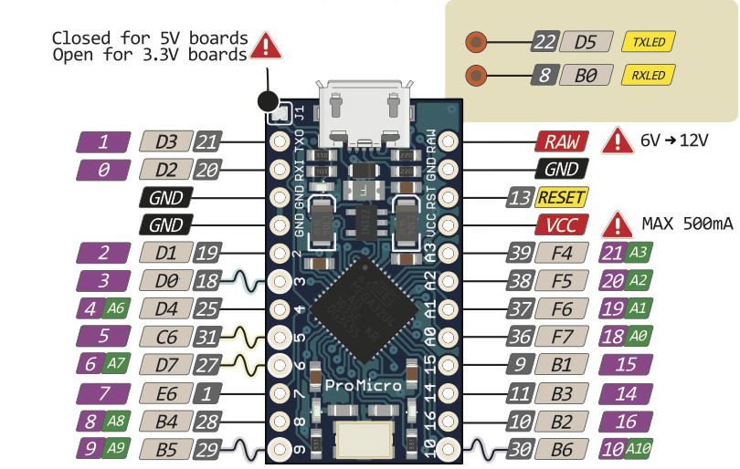
The Pro Micro board has 24 pins total, of which 18 are usable in a GPIO context. Its microcontroller, the ATMega32U4 can support more GPIOs, but they’re not broken out on the standard Pro Micro board (though some boards like the Elite-C break these out on extra pins at the end).
With a perfectly optimal square key matrix (and no other cool features like LEDs, encoders or OLEDs) you could squeeze out a 9 x 9 = 81 matrix. Enough for a 65% board, but pretty limiting for a 75% board unless you want minimal layout options (though not impossible!). Thankfully there are ways to work around this limitation.
Memory
The other limitation with Pro Micros is the limited program memory that they have. This is a result of the ATMega32U4 controller having 32kb of program memory. Depending on what features you want to run on your board, you may or may not run into this limitation, but in my experience, when I’ve wanted to add Vial compatibility, many layers, RGB lights and more, I’ve hit the dreaded “The firmware is too large!” error.
How do you work around them?
As I mentioned earlier, one of the fun challenges for me in designing keyboards is to work with and around the imposed limitations that we have – and the matrix design is where the fun happens.
Change up the matrix shape
Probably the simplest thing that you can do to squeeze more out of a Pro Micro without adding complexity is to ensure that your matrix is as optimal as possible. And optimal in this case means as square as possible as that maximizes the keys available per pin count.
If you wanted to support 64 keys in a matrix you could have 5 rows and 13 columns in your matrix. 5 x 13 = 65 and 5 + 13 = 18 so you would use all possible GPIO on the Pro Micro to get this layout. But you could instead morph the matrix to make it more square, conveniently 8 x 8 = 64 and 8 + 8 = 16 which would result in a saving of 2 pins. These 2 pins could then be used for an encoder or an OLED screen.
There’s a slight downside here in that it complicates the firmware mapping slightly, but this complication doesn’t extend to end users (they will still see the correct layout when using Via or Vial assuming you’ve mapped everything correctly).
As a practical example here, this is exactly what I did when designing the Litl keyboard. It’s a 40% Pro Micro powered board and has a rotary encoder and an OLED or, optionally, two rotary encoders. The OLED requires 2 pins and each rotary encoder optimally requires 2 pins too. So I had 18 - 2 - 2 = 14 GPIO pins to use for the matrix.

The physical layout that I wanted was 4 rows x 12 columns which would use a total of 16 pins. Something not possible if I wanted to keep the OLED and encoder there. A better way of supporting 4 x 12 = 48 keys was to use a more square matrix. 7 x 7 = 49 keys and 8 x 6 = 48 keys (and both used 14 pins) so these were more optimal configurations.
I ended up going for the 8 rows by 6 columns matrix option as that ultimately meant that I could just double up the rows in Kicad so it was easier to lay out.

In the matrix layout of the Litl above you can see that each physical row actually has two pins connected to it, with every other switch being on a different pin. Physical columns are grouped in pairs (to halve the total number of columns) and connected to a shared pin.
This solution worked great in the end, the matrix worked as expected and the firmware was not too tricky to configure (you can see the layout mappings here). Later on I learned that this type of matrix actually has a name: a folded matrix or a ‘western’ duplex matrix.
Alternative matrices
The previous solution worked great for the 40% board that I was designing, but it sadly doesn’t scale so well as it’s not possible to make the standard matrix any more optimal than a square. This is where alternative matrices come in.
Instead of connecting every key to a single diode facing the same way and scanning the matrix in the standard ROW2COL or COL2ROW fashion you could try alternating diodes and scanning the matrix both ways. This is called a Japanese duplex matrix and is a really neat solution. I won’t go into too much more detail as there’s a great write up here on kbd.news, click the link above.
There are even more inventive matrices that you can try like the Square or Round Robin matrix which supports more keys still (though it comes with its limitations).
Use some additional hardware to extend the matrix
The alternative matrices can very well work for larger boards, but there are some limitations to contend with, so when designing our 65% board, Lagom, I looked at adding a few small additional components to support the larger matrix required.
To understand why I would do this, you might need a little more background about how a keyboard matrix works. Quoting directly from the QMK documentation:
“When the circuit is arranged in rows and columns, if a key is pressed, a column wire makes contact with a row wire and completes a circuit. The keyboard controller detects this closed circuit and registers it as a key press.
The microcontroller will be set up via the firmware to send a logical 1 to the columns, one at a time, and read from the rows, all at once – this process is called matrix scanning. The matrix is a bunch of open switches that, by default, don’t allow any current to pass through – the firmware will read this as no keys being pressed. As soon as you press one key down, the logical 1 that was coming from the column the keyswitch is attached to gets passed through the switch and to the corresponding row.
In the background above columns are periodically having logical ones sent to them with the reading (and hence detection of a keypress) being done on the rows. Typically each pin will correspond to a column or a row. But in the case of the columns here, we don’t necessarily need a separate pin on the microcontroller to send out a logical one. We could find a way of connecting one pin to multiple columns (or more pins to even more columns). The only thing that we need to keep track of is which column had a logical one sent to it, so that we can identify the key pressed when we see a row being read as a one too.
There are at least two ways how this one pin to many column setup can be done, via a demultiplexer or via a shift register. Both routes will ultimately enable a few pins to control the output of many columns.
Shift registers
A shift register ultimately converts between serial and parallel data formats. Different shift registers can have different formats and types of conversion, but for what we want to do here, a serial to parallel shift register like the 74HC595 series is suitable. This takes data in a serial format (i.e. sequential data) and converts it to a parallel format (i.e. many bits sent at the same time). The serial data that you send only requires 3 pins from the controller: a latch, a clock and a data pin. The 74HC595 series is an 8 bit shift register so will be able to control 8 columns from 3 pins, however it can be daisy chained together to enable control of even more columns with the same number of controller pins. There’s a great example of this used in a keyboard context here where 3 pins control 16 columns.
One slight disadvantage of using additional componentry for a keyboard matrix is that you need to write or adapt custom matrix scanning code to handle the shift register. This isn’t something super complex but it’s something to be aware of.

Demultiplexers
Another way of using additional hardware to extend the matrix is to use a demultiplexer. This is an IC that has n inputs and converts this to 2 ^ n outputs. In this way you can use n pins on the microcontroller to control 2 ^ n columns in the matrix. This is the route that I went for when designing our 65% and 75% boards.
I specifically used a 74HC138N IC that takes 3 inputs and provides 2 ^ 3 = 8 outputs. I needed to support 16 columns for the board, so I had to use 2 of these ICs with 4 controller pins to operate them. When I wanted to scan columns 0 to 7, I used the first IC and ensured that the second IC would not output anything, and when I wanted to scan columns 8 to 15 then I did the opposite and activated the second IC and ensured the first one would not output anything. The wiring that I went with looks like this:
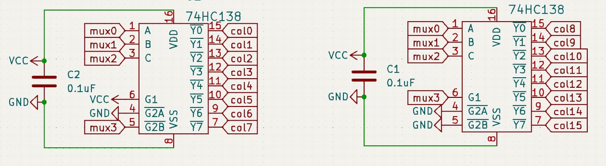
The pins controlling the ICs are mux0 to mux3 with mux3 being the pin that activates or deactivates each IC when scanning the other 8 columns. As with the shift register example I had to use custom matrix scanning code, but it is generally simpler as there is no conversion of serial to parallel happening.
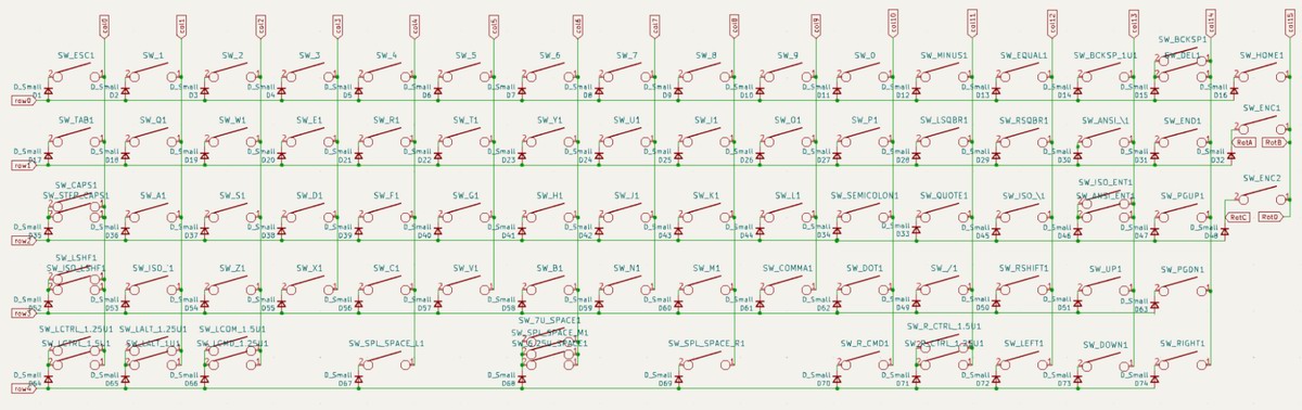
For our Lagom 65% board I wanted to support various layouts and settled on the key matrix shown above. By using demultiplexers I was able to reduce the total pins needed for the keys to 9 (5 rows and 4 columns).

Even more efficient usage of Pro Micro GPIO pins than the Litl board meant that I could support more cool features on the board. In the case of Lagom 65% (above), I added two rotary encoders, an OLED screen and optional LED underglow to use 7 more pins for a total of 16 GPIO pins.
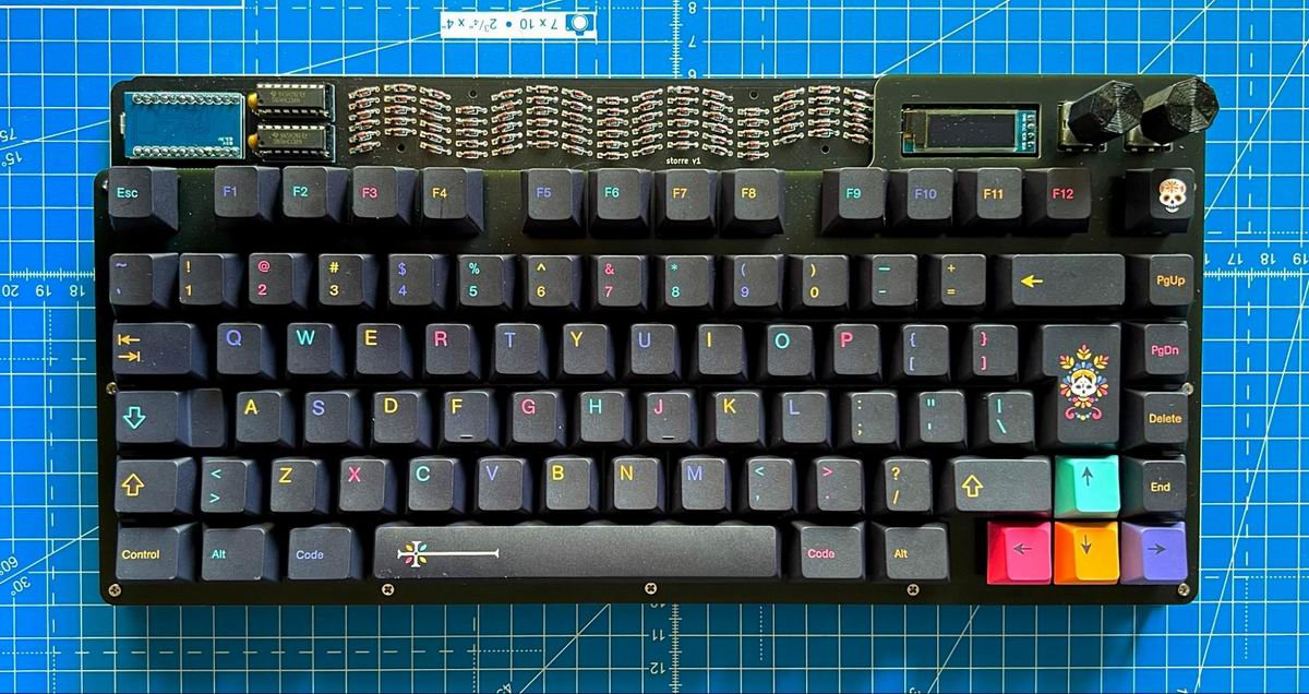
Careful readers will notice that there are still 2 spare GPIO pins available! This meant when I was designing Större, our 75% shown below, I could use almost the same layout but utilise one of those additional pins to support a new row with minimal changes to the schematic!

Using multiple Pro Micros
Perhaps this is slightly cheating as it uses multiple Pro Micros, but a perfectly possible solution for supporting larger keyboards would be to take a page out of the split keyboard handbook and use more than one!
In the example of many split keyboards, each half has a dedicated controller, with one controller being connected to the computer (typically with USB) and the other controller connected to the first controller (typically by serial or i2c and connected with a TRRS cable). But you don’t have to have a split keyboard to use multiple controllers within a keyboard.
You could, for example, have the main part of the keyboard powered by a single controller with an additional controller, connected on the same PCB (i.e. not via a cable) via i2c or serial, powering the numpad cluster and macro keys (or even more). This way you could build up a control center 100%+ keyboard all powered by venerable Pro Micros.
I’ve not verified this, but you could possibly have more than two controllers in a split configuration to create an even bigger setup, but I think you’d have to update the QMK split code considerably.
Memory Limitations
The memory limitation with the Pro Micro is a little trickier to work around, but still completely possible to do. There are two angles of attack here, one is using the standard Pro Micro with the ATMega32U4 controller and trying to squeeze the most out of it, and the other is changing to a newer controller with more program memory and sidestepping the limitation entirely.
With the standard Pro Micro you’re a little more limited as you only have 32kb of program memory to play with. If you’re using vanilla QMK with few special features this will be a non-issue, but if you’re using Via or Vial, have an OLED and LEDs then you’ll be taking up more memory.
I’ve found the Vial guide to reducing firmware size to be a good start here. Starting from a relatively clean slate where you have the bare minimum that you need and then adding features that you want one by one to see what takes it over the firmware size limit has worked for me before. I didn’t use the majority of the RGB animations (and only really cared about a couple) so there were some easy things to cut that made no practical difference.
The same goes for the OLED animations, they can be quite heavy, so look into refactoring or optimizing them if that’s causing you to go over the limit. As a final step, once you’ve figured out your perfect layout, you could move away from Vial and compile your perfect configuration to QMK to save some more bytes.
A newer controller sidesteps all of these issues. The most popular ones that I’m seeing now are RP2040 based – and these have far more program memory so you won’t be running into any of the issues – 16Mb flash memory in some cases! There are many that are pin identical to the standard Pro Micro and the process of porting firmware to them and flashing them is relatively straightforward now (in any case this QMK page is a great place to start).
Given various chip shortages over the last couple years you might also be surprised to see that RP2040 Pro Micros are sometimes even cheaper than their Atmel equivalents! So all in all they’re a really great option for a Pro Micro compatible board.
Conclusion
In conclusion, the journey with Pro Micros in designing keyboards for STHLM kb has been both rewarding and challenging. Despite their limitations, these tiny microcontrollers have proven to be a cornerstone in the world of keyboard design for their simplicity, flexibility, and affordability.
There are a great number of creative solutions, such as optimizing matrix shapes, exploring alternative matrices, and integrating additional hardware components like demultiplexers and shift registers. While memory constraints remain a challenge, newer controllers like the RP2040 offer expanded capacity. Nevertheless, the Pro Micro's enduring presence continues to drive creativity and problem-solving, cementing its foundational role in keyboard design as newer alternatives emerge.
I’m sure there are many other wonderful matrix designs and truly wacky Pro Micro based keyboards out there – so please share your experiences and boards you’ve made!
| Moses Hoyt (34) |
|---|---|
| Handle | mohoyt, mojibber |
| Location | Stockholm, Sweden |
| Description | Keyboard designer |
| Occupation | Product Manager |
| Joined (the hobby) | 2020 |
| Niche | DIY keyboards |
| Fav. switch | Gateron Oil King and Milky Yellow |
| Fav. keycap profile | XDA |
| Other hobbies | Cooking, Crossfit, Synthesisers |
| Links | sthlmkb.com, mohoyt.com, github.com/mohoyt |
References
- https://kbd.news/Square-or-round-robin-matrix-1400.html
- https://kbd.news/The-Japanese-duplex-matrix-1391.html
- https://sthlmkb.com
- https://mehmedbasic.dk/post/74hc595-keyboard/
- https://docs.qmk.fm/#/feature_split_keyboard
- https://get.vial.today/docs/firmware-size.html
- https://docs.qmk.fm/#/platformdev_rp2040
Published on Sun 3rd Dec 2023. Featured in KBD #2023.
Related

How to organize a keyboard meetup
Gordon Diggs, the man behind the NYC Mechanical Keyboard Meetups, gives us some tips on how to organize a meetup.
Building keyboards with lasers
Ming-Gih Lam walks through the process of how to build keyboard cases using vector graphics software and a laser cutter.
Forcy McForceFace
Jesse Vincent, cofounder of Keyboardio, describes building a force tester out of an old 3D printer: Forcy McForceFace.
QMK RGB Matrix configuration
The focus of Sadek Baroudi's tutorial is how to properly configure RGB Matrix especially for non-trivial ergo keyboards with angles and column stagger.