Keyboard Builders' Digest / Tips & Tricks
Quantum Painter tutorial
How to add Quantum Painter/color LCD to (almost) any QMK keyboard – a tutorial by Esse Woods aka OakNinja .

Published April 5, 2024

This text is also available on Github and Medium.
When I first started looking into Quantum Painter, QMK's standardized API for graphical displays, I tried to find a simple example on how to get it up and running.
I'm not a complete hardware n00b, but while the documentation for Quantum Painter is well written and extensive, I still found it hard to put all the pieces together. Understanding the RP2040 pin configuration, the SPI protocol, how Quantum Painter worked, and so on and then stitching it all together was not obvious to me.
After getting some help in the QMK discord, I managed to get my first display working – a two inch 320x240 LCD using the ST7789 driver. After getting the basics up and running, I decided to create a simple display-only keyboard that can be used to test different LCDs and get a basic idea what is needed to get Quantum Painter up and running.
Also, I wanted a configuration that would be widely compatible with almost any Elite Pi/RP2040 based keyboard, making it possible to add a color LCD using Quantum Painter to an existing keyboard.
So here it is – The Guide I wish I would have found when I started looking into Quantum Painter.
Let's start by going over some nomenclature.
- QMK – The keyboard firmware
- Quantum Painter – The feature in QMK that makes it possible to easily show graphics on different LCD's.
- Controller – The hardware that QMK runs on. Only RP2040 based controllers can use Quantum Painter. Pro Micro controllers won't work.
- SPI – The protocol used to communicate between the controller and the display.
Pins
One of the things I found it hard to wrap my head around was which pins that could/had to be used on the controller. I wanted to use the "Extra" pins on the bottom of the controller (12,13,14,15 and 16) since these are rarely used and would make it a lot easier to add a display to more or less any keyboard. While possible to use other pin configurations on the rp2040, the configuration we will use on this keyboard will utilize the extra pins.
Elite Pi compatible controllers (I use the Liatris from SplitKB, but any Elite Pi compatible controller should work) have two SPI channels, SPID0 and SPID1. These two different channels have a bunch of different possible configurations, but only SPID1 can be used on the extra pins.

If you look at the image above, you can follow the teal labels for SPI. Please note that what is called DX, e.g. D1-D29 on the image above, is called GP1-GP29 in QMK. Also, do not mistake the orange I2C labels with the SPI ones – they are not the same protocol.
To connect an LCD display to the RP2040 over SPI, you need to connect seven pins

- GND -> Ground
- VCC -> VCC
- SCL -> SCK1 (Clock)
- SDA -> TX1 (Data/MOSI)
- RST -> Any available pin on the RP2040
- CS -> Any available pin on the RP2040
- DC -> Any available pin on the RP2040
As mentioned, there are two SPI channels on the RP2040: SPID0 and SPID1.
The only pins that must be connected to specific pins are VCC, GND, SCL, and SDA. All other pins can be connected to any unused pin on the RP2040, as long as they are properly configured in QMK.
So, valid configurations for SPI channel 0 (SPID0) would be:
- Any of the pins D2, D6, D10, D22 for SCL/SCK.
- Any of the pins D11, D3, D7, D23 for SDA/TX/MOSI
- RST, CS and DC can be connected to any unused pin
Valid configurations for SPI channel 1 (SPID1) would be:
- Any of the pins D14, D26 for SCL/SCK.
- Any of the pins D15, D27 for SDA/TX/MOSI
- RST, CS and DC can be connected to any unused pin
Several SPI devices can be connected to the same channel as long as the CS (Chip select) pin is separate for the different devices.
So, while the first device will require five pins, any additional device will only require one more unused pin and can share the rest with the other devices on the same channel.
I won't go through connecting several SPI devices on the same channel in this guide, but it can be good to know that it's possible.
Enough talk. How to get going?
This firmware uses the extra pins on the bottom of the controller, pins 12, 13, 14, 15, and 16. You will also need to wire up VCC and GND (available as pads on most PCBs, otherwise they can be wired directly to the controller)
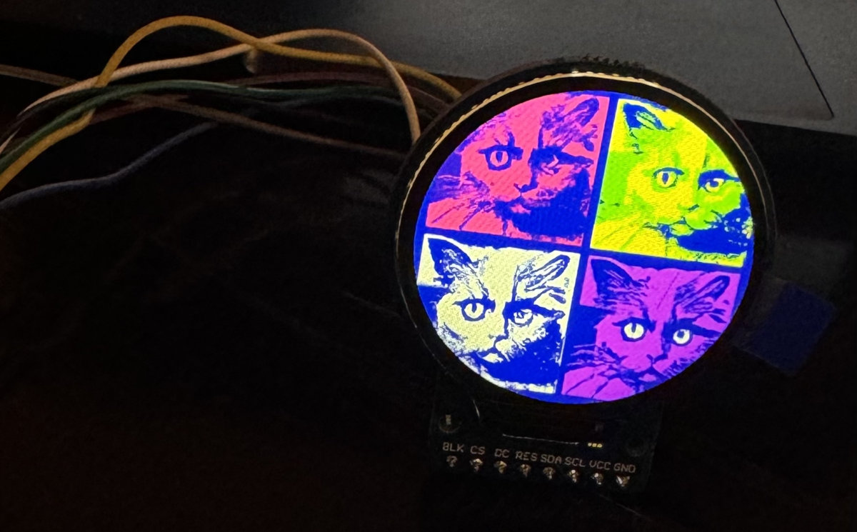
I've built two ready to go keyboard configurations (github). One for a 2" 320x240 st7789 display, and the round GC9A01 1.28" 240x240 display.
To build these, run
make qp_display_only:default to build the st7789 firmware,
and
make qp_display_only:gc9a01 for the GC9A01 firmware.
This keyboard is intentionally created as simple as possible in order to make it easy to add Quantum painter to your own keyboard.
Some important notes
- In config.h, you can set SPI_MODE. There is four modes, 0,1,2,3. The documentation for your display _should_ describe what mode you need to use. However, if you don't get any output on your screen, you can just try the different modes by changing the SPI_MODE in config.h to any of these four modes and reflash your controller.
- If the colors are inverted, set #define LCD_INVERT_COLOR in config.h.
- If you still don't have any image on your screen, try playing around with the LCD_SPI_DIVISOR value. Try to set it to a higher value, like 32.
- If you have a display with a different resolution, set LCD_WIDTH and LCD_HEIGHT in config.h. For this keyboard, they are set in the keymap/config.h
Ok, so I got this firmware working for my display, how do I move it over to my keyboard?
Copy halconf.h to your keyboard firmware
Add these fields to config.h:
- #define SPI_DRIVER SPID1
- #define SPI_SCK_PIN GP14
- #define SPI_MOSI_PIN GP15
- #define SPI_MISO_PIN GP20 // Unused
- #define LCD_RST_PIN GP16
- #define LCD_DC_PIN GP12
- #define LCD_CS_PIN GP13
- #define LCD_BLK_PIN GP7 // Unused in this configuration
- #define LCD_SPI_DIVISOR 4
- #define LCD_WAIT_TIME 150
- #define LCD_ROTATION QP_ROTATION_0
- #define LCD_OFFSET_X 0
- #define LCD_OFFSET_Y 0
- #define LCD_WIDTH 320 // Set according to your display specs
- #define LCD_HEIGHT 240 // Set according to your display specs
- #define SPI_MODE 2 // Set according to your display specs
- #define ST7789 // Set according to your display specs
- #define QUANTUM_PAINTER_SUPPORTS_NATIVE_COLORS TRUE
- // Timeout configuration, default 30000 (30 sek). 0 = No timeout. Beware of image retention.
- #define QUANTUM_PAINTER_DISPLAY_TIMEOUT 0
Copy the gfx folder to your keyboard firmware
Add the code from qp_display_only.c to keyboard_post_init_kb in your firmware.
Generating images
To generate your own images, and even animated gifs, you can just convert an image with the same size as your display.
The qmk painter-convert-graphics command converts images to a format usable by QMK, i.e. the QGF File Format, e.g.:
qmk painter-convert-graphics -f rgb565 -i my_image.gif -o ./generated/
I resize my images before running the conversion. You can let the converter resize your image for you, but in order to get the best possible result I find it easier to resize the image first. See this part in the quantum painter docs for more info.
Thanks to :)
I would never had been able to sort this out without the help of tzarc, elpekenin and honorless on the QMK Discord.
Additional reading
- This text is also available on Github and Medium.
- Find other Quantum Painter enabled firmwares: qmk -find -f features.quantum_painter=true
- https://docs.qmk.fm/#/quantum_painter
- https://discord.com/invite/qmk
Published on Fri 5th Apr 2024. Featured in KBD #160 (source).
Related

Lattice60
PrimeNumber shared the files of the handwired Lattice60, an ortholinear keyboard with standard keycaps and low-poly case.
The SpaceFN concept
The SpaceFN concept - setting up your space key as a layer switch when held - is probably one of the most useful tweaks in the keyboard hobby. Let me explain it.
Keyboard Case Design
Sadek Baroudi provides a detailed walkthrough of how he designs 3D models – Starting with a PCB, and ending with a model that you can export for 3D printing.
From switchbody to 3D keywell
Chris Trotter's Fusion360 tutorial details how to design custom parametric keywells, used e.g. for his ArcBoard.