Keyboard Builders' Digest / Tips & Tricks
The (Japanese) duplex matrix
There are two completely different keyboard matrices referred to as duplex matrix. Let's examine the Japanese one, which makes possible to handle 160-200 keys with a single Pro Micro.

Published April 25, 2022
This topic would deserve a much more comprehensive write-up but let me do a quick post now since I've referenced the "Japanese" duplex in more and more posts recently – without a proper explanation.
Some parts, especially the code part, need further examples, but I decided to publish this anyway.
If you are a member of the Japanese DIY keyboard community, you've most likely heard of this concept. If you are a pro, feel free to skip the introduction and head right to the Japanese duplex part.
Otherwise, let's see how to handle 200 switches with a single Pro Micro (and in a later post we'll cover how to increase that to 380 keys).
The duplex matrix conundrum
What is a duplex matrix?
I thought I knew it full well until about two weeks ago when, during a chat with @policium on the PRK firmware, I had to realize we are talking about two entirely different matrices.
It seems the term "duplex matrix" can denote two fundamentally different wiring/arrangement method depending on which part of the world you live.
Duplex-matrix as we call it in the US and Europe seems to have a different meaning than it does in Japan. (Sorry, I'm not sure about other parts of the world.)
For the sake of reference, let's call the first one the Western duplex and the second the Japanese one. Despite the identical name they have totally different purposes and effects on the number of required pins.
- Western duplex matrix: this is in fact a basic matrix folded along the row plane. Helps to get closer to the ideal (square) matrix but can't increase the number of potential keys.
- Japanese duplex matrix: this is a more sophisticated matrix, scanned in both directions. Can double the keys handled via diodes in alternating directions. May require meddling with the firmware code.
Naming controversy
So why do we use the term "duplex matrix" for two entirely different matrices?
@policium says the term was misused by ai03 in his popular reference work on PCB design and has been spread and became established.
When I made it and named it, I was a high school student with little knowledge of electronic circuits, so I didn't know the true Duplex – ai03 (source).
Indeed, Duplex [communication system] is usually a system where two parties communicate in both directions. In the western duplex there is only one direction (col2row or row2col) so the appellation is not the aptest one to say the least.
However, the term "duplex" itself has multiple meanings too: ranging from double and folded to simultaneous bidirectional – depending on your language, location and field of interest. So simply stating that the name fits one or the other matrix better may not be appropriate.
Regardless, the most important point of this write-up is that in the Japanese duplex the matrix is scanned in both directions, thus, doubling the number of keys!
According to e3w2q's awesome article on the topic (featured in the traditional Keyboard Advents Calendar 2019), in the Japanese keyboard community the genuine duplex matrix is attributed to Mr. Apuro (source).
Let's start with a vanilla Pro Micro which has 18 easily accessible GPIO pins.
And let's start at the very beginning: direct connection.
Direct connection
In the most basic arrangement, connecting switches directly to the GPIO pins of the controller/development board, you can handle only 18 keys with a Pro Micro.
This may be perfect for small macropads, numpads, and there are many minimalist 36-key splits where 18 pins (for one half) are just enough.
But of course for many other projects the number of pins/keys can be an important limitation.
This is when matrices come into play.
Basic keyboard matrix
Arranging the switches into a grid, more specifically into columns and rows, and using the pins to address/read the state of those columns and rows of switches, we can scan the matrix and monitor the state of all the keys.
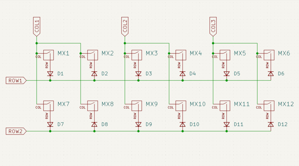
Let me draw a smaller matrix as a demonstration, a 6x2 one.
As you can see, we used 6+2=8 GPIO pins altogether. Instead of 8 switches (direct pins), however, we manage 12 keys this time!
It works the other way around too, with diodes pointing to the opposite direction.

So as long as you are consistent with the diode direction, both arrangements work. (Assuming, of course, you set the proper direction in your firmware.)
According to this concept, QMK for example offers the COL2ROW or ROW2COL constants to set the method the matrix is scanned (and DIRECT_PIN too ofc).
But wait! We used 8 pins for 12 keys, right? In an optimal case (a 4x4 matrix) that would mean 16 keys.
Ideal matrix
Exactly. And it looks even more painful when we utilize all 18 pins of a Pro Micro. We could arrange the 18 pins into a 9x9 grid, which means 9x9=81 switches can be handled in the ideal case. "Ideal" here means the square arrangement, when the number of rows equals the number of columns.
Unfortunately, and that's a pretty common case with keyboards, when the number of columns is higher than the number of rows (or the other way around), we actually waste some pins. Or lose some keys – depending on your POV.
9x9=81, 8x10=80, 7x11=77, 6x12=72, 5x13=65, 4x14=52… Ouch.
As you can see, we can handle less and less keys despite using the same number of pins.
Is there a way to get back to around 81? To increase the number of keys or spare some pins? Sure! The "Western" duplex matrix is what you need.
Folded matrix – or the "Western" duplex matrix
(It's fun to call this the Western one because ai03, whose guide helped to spread the term, is actually Japanese too if I'm right.)
So the Western duplex isn't really a new kind of matrix. It's the same as the basic one. It can be scanned as COL2ROW or ROW2COL which means it isn't really "duplex" in the sense of the word used in telecommunication where it often refers to a bidirectional messaging option ("two messages may be sent simultaneously in opposite directions over a single circuit").
As you can see, the Western duplex is nothing more than a cramped basic matrix, folded into two along the rows.
We seemingly use the same COL pin for two physical columns of keys and double the number of rows – closing in on the optimal matrix shape. (But in reality those two columns are one, only bent in an U-shape.)
E.g. a 4x14 basic matrix can be turned into a 8x7 Western one, and we can cover the same 52 keys with less pins: (4x2)+(14/2)=15.
Wait, what?! That's actually awesome! The same number of keys handled by just 15 keys instead of the original 18! We spared 3 pins with this simple trick.
Indeed. This "Western" kind of duplex matrix may come in handy for several projects, but we are still below 81 keys. Not to mention 200 switches. Hold on, we're getting there.
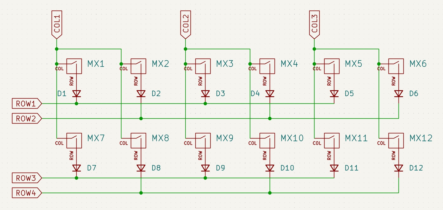
Japanese duplex matrix
How is the Japanese duplex matrix different? It scans the matrix in both directions! First COL2ROW, then ROW2COL – in succession.
The trick lies in the direction of diodes: two columns are connected to the same COL pin, but one column has diodes pointing in one direction, while switches in the second column have diodes pointing to the opposite direction.

Note the diodes pointing to the opposite direction. One column has COL2ROW diodes, the next ROW2COL ones.
This way the matrix can be scanned in both ways, checking half of the switches on the COL2ROW and another half on the ROW2COL iteration.
Compared to the Western duplex, we need only half the rows here.
For the same 12 keys in the examples above,
- We used 12 pins with direct connection.
- Do you remember the basic matrix? We needed 8 pins with that (6+2).
- With the folded Western duplex? Only 7 pins (3+4).
- The Japanese one? Just 5 pins (3+2)!
The larger the layout the more dramatic the number of spared pins is. What about a classic ortho board, e.g. the Preonic (12x5=60 keys)?
- Direct connection: unfeasible.
- Basic matrix: 12+5=17 pins
- Folded Western duplex: (12/2)+(5x2)=16 pins.
- Japanese duplex: Just 11 pins!
For this to work, however, you might need to hack your firmware.
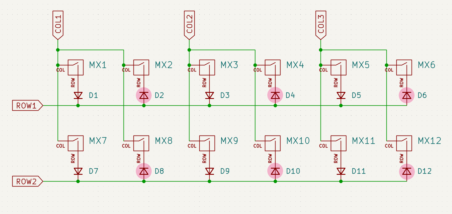
Ghosting
At first sight you might think that this arrangement and scanning will result in a lot of ghosting – unpressed keys registering.
Well, that's the beauty of this matrix: by choosing your electronic components carefully, you can ensure that by the time the signal passes three diodes, it won't trigger a false positive.
")
In the picture above, pressing/holding switches 1, 4 and 9 at the same time could theoretically cause ghosting (MX7). However, that isn't the case with real-life diodes.
According to my measurements, passing two 1N4148 diodes registers as a keypress every time. But there wasn't any keypress registered by a (5V) Pro Micro with three diodes!
The point is, you have to carefully plan your component choice. This may involve some measurements both on the diode (forward voltage drop) and the controller side (thresholds of LOW and HIGH). In any case, you can use two diodes instead of one (for each key, or as we will see at the improved square matrix: an extra diode for each pin).
Firmware
Unfortunately, for most keyboard firmware, you have to write your own matrix scanning algorithm for this to work, e.g. to rewrite the matrix.c file in QMK.
Let me not paste a bunch of code here. e3w2q has his matrix.c published here – check out how that works.
In addition, sqeezeonein points out that there was a pull request addressing this feature in QMK as well (here) – by elfmimi/a_p_u_r_o. Sounds familiar? ;)
If you are too lazy to implement this, PRK firmware has this function built-in (source). So you can try this concept right away, at least with RP2040-based controllers.
Now you know what @policium meant by telling us in the PRK piece:
PRK is developed by crazy people, so they implement maniacal features before they implement normal features.
---
Well, that's it.
After reading through all this wall of text, some readers may find that this kind of matrix deserves the duplex matrix name because of the bidirectional scan.
Only one question remains: How should we reference the "Western duplex matrix" from now on?
Let me know your ideas and preferences.
Hey, you babbled about 160-200 keys…
Yeah, sorry.
So with 18 pins of the Pro Micro we handle 81 (9x9) keys with the basic matrix and double that (162) with the Japanese duplex presented here.
However, with another old little hack, by utilizing the two LED pins of the Pro Micro, you get 20 GPIO pins or 10x10=100 keys (basic matrix). Double that with the Japanese duplex and voilá: you have 200 keys.
Real-life usage
I'm not suggesting you need 200 keys.
I'm saying that the pins you save with a duplex matrix can be used for whatever you want: LEDs, rotary encoders, displays, more keys, you name it.
It turns out you can use a Pro Micro, KB2040 or similar cheap controller to build even a fullsize keyboard. (Why would you do that is a different question.)
What's next?
With even more sophisticated matrices, still using the voltage drop across the diodes to avoid ghosting, you can almost quadruple the number of keys – that means 380 keys with 18 pins of a humble Pro Micro. That's the square or round-robin matrix.
---
Sources
- Duplex-Matrixを自作キーボードで使う方法
- https://wiki.ai03.com/books/pcb-design/page/matrices-and-duplex-matrix
- https://github.com/e3w2q/qmk_firmware/commit/762fe3e0a7cbea768245a75520f06ff5a2f00b9f
- PRK firmware wiki – Duplex matrix
Published on Mon 25th Apr 2022. Featured in KBD #75.
Related

Kazik
Kazik is a cute 30% keyboard by monokēēbs – with versatile PCB, XIAO RP2040, and Japanese duplex matrix!
Square or round-robin matrix
Let me introduce the square or round-robin matrix (aka Charlieplexing for keyboards) – a very tricky one promising 380 keys with a single Pro Micro.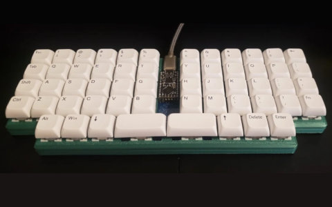
JESK56
T. G. Marbach's JESK56 is a diodeless 56-key ortholinear keyboard, using a single RP2040-based microcontroller thanks to some fancy math and graph theory.
Maximising the effectiveness of Pro Micros in keyboard design
Moses Hoyt, from STHLM kb, shares his challenges, tips and tricks for overcoming the limitations of Pro Micro controllers in keyboard design.