Keyboard Builders' Digest /
A brief history of keyboard encoding
Daniel shares with us some of the fruits of research into computer keyboard history conducted over recent years. In this case, the surprising variety of methods by which keyboards determined which keys are being pressed.
Published December 8, 2023
Overview
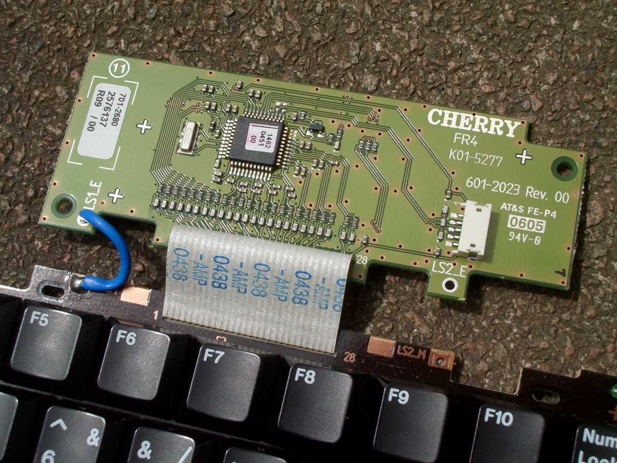
The implementation of modern computer keyboards is fairly common knowledge within the keyboard enthusiast community. Regardless of the switch technology, the switches are wired into a grid or matrix formed on a printed circuit board or set of membrane sheets or, in some custom keyboards, by hand-wiring directly. Firmware stored in a microcontroller—a microprocessor (CPU) with built-in RAM, ROM and I/O—examines each key in the matrix in turn to see whether it is pressed. With mechanical (metal contact) and membrane switches, the firmware allows time for the switch contacts to settle before reporting a keystroke. A look-up table in ROM provides the identity (scancode or usage code) of the key at each matrix position. The encoder (commonly but incorrectly referred to as the “controller”) communicates keyboard activity to the host computer.
This was not always the case, however. For starters, microprocessors didn’t reach the market until 1970 and electronic keyboards go back at least a decade before that. Even in 1970, using a microprocessor for a keyboard would not become a viable option for years.
So, how did keyboards work in the early days, and what techniques had to be adopted to create a practical keyboard?
Early techniques
In addition to detecting keystrokes, keyboards need a way to identify and report which key is being pressed. This process is known as “encoding” and the hardware that accomplishes it is called the encoder. Most readers will expect a single chip to handle all of this, and will be confused when they instead encounter a mass of circuitry or a huge bank of diodes in a decades-old keyboard. What is going on in these old products?
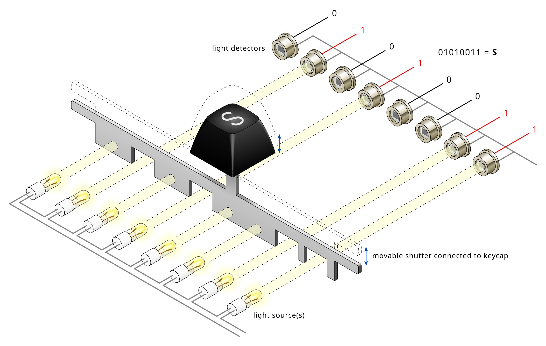
As early as 1960, Invac designed light-beam keyboards, originally attached to mechanical typewriters (US patent 3032163) but soon offered as devices in their own right (US patent 3092310 and advertised at least as early as 1962). A set of parallel light beams crosses the keyboard from one side to the other. A notched shutter is attached to each key: pressing the key blocks a specific selection of the light beams. Photodetectors read the resulting pattern as a binary code.
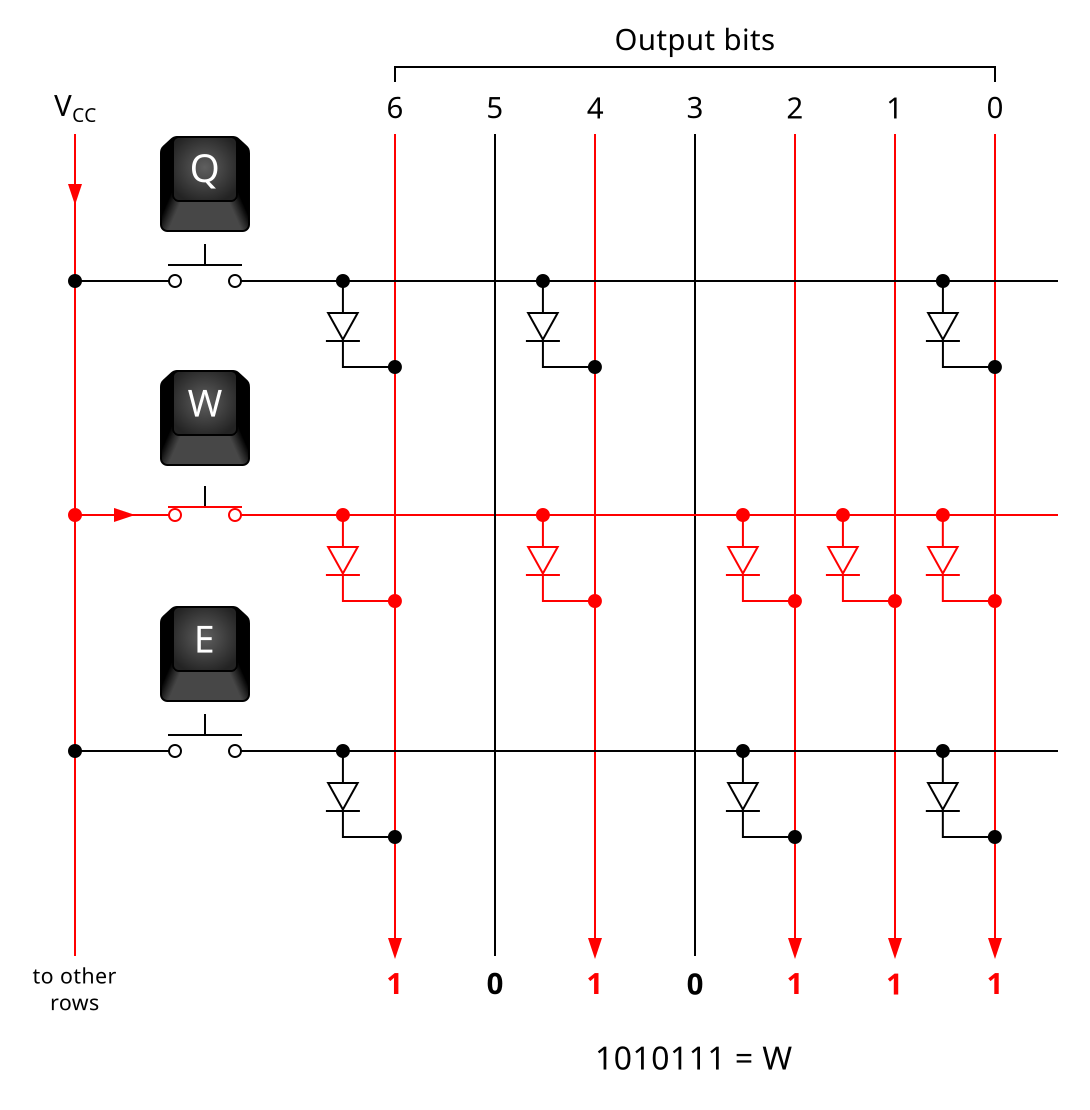
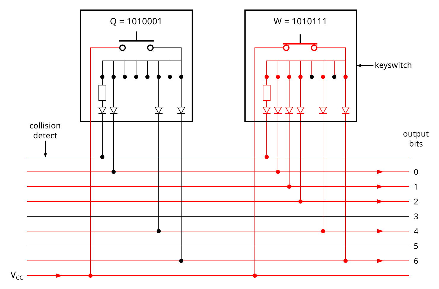
By the late 1960s most keyboard manufacturers favoured purely electronic keyboards instead of photoelectric and electromechanical. The most common encoding technique became the diode matrix, used by various manufacturers in the 1960s and early 1970s. A diode matrix is simply a bank of ROM constructed from a grid of discrete diodes; this approach pre-dated semiconductor ROM. A grid position linked by a diode registers as a 1, and the absence of a diode as a 0.
In a basic diode matrix keyboard—there seem to be some more exotic arrangements—each key is wired to a row of the grid. The selection of diodes soldered into the row determines the key’s output code. Pressing a key feeds current into that row which then passes through the diodes into the columns, where the code is read off. (Diodes are used otherwise you would get a problem akin to ghosting.)
Diode matrices require considerable space, sometimes as much as a whole PCB to themselves as with the Potter Instrument KDR/KB 3100A. George Risk Industries however mounted the diodes vertically on rails along the edge of the switch PCB, as seen in the model 2-103-001-A-10. Diode matrix encoding was perhaps most commonly paired with reed switches.
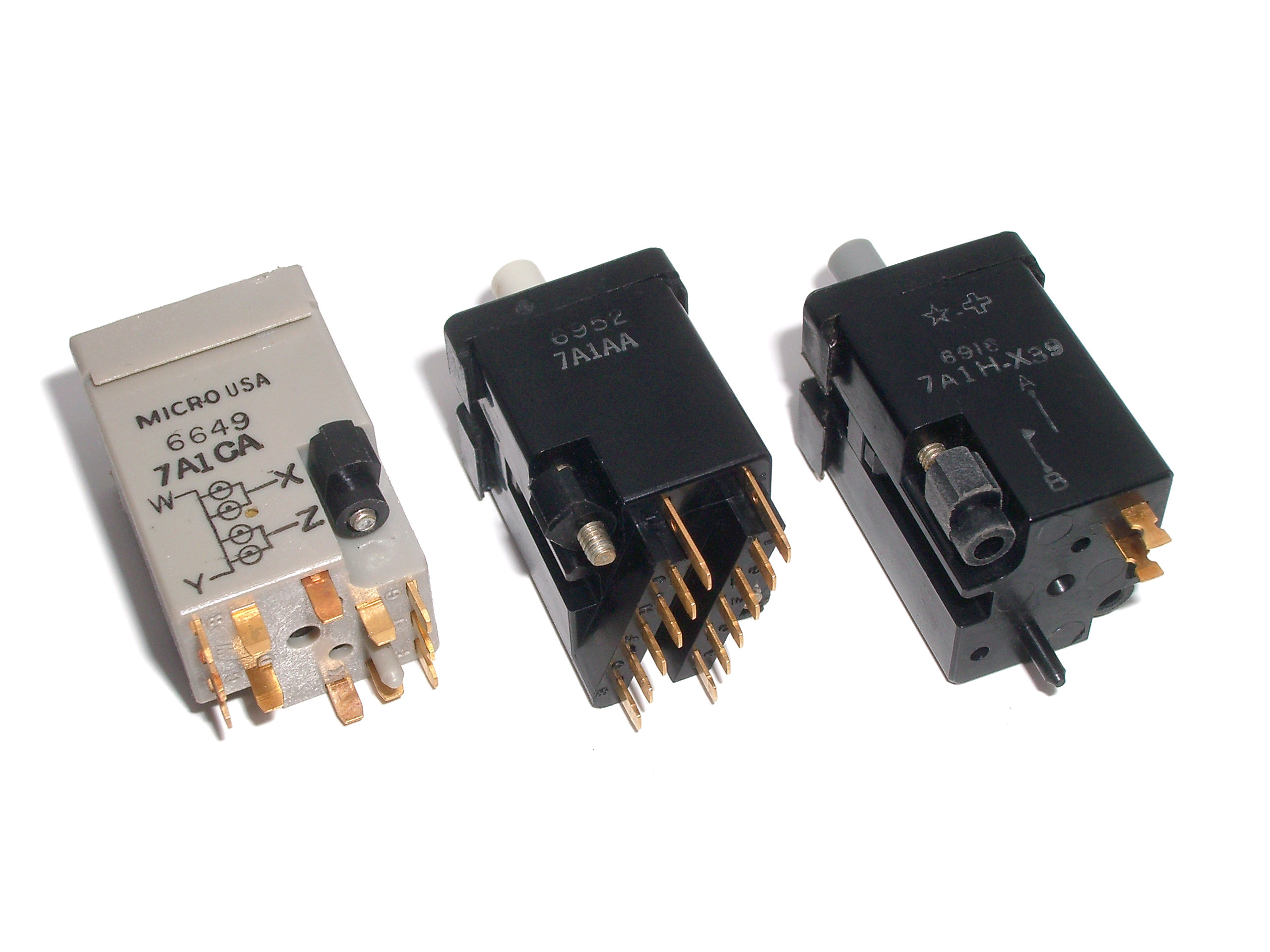
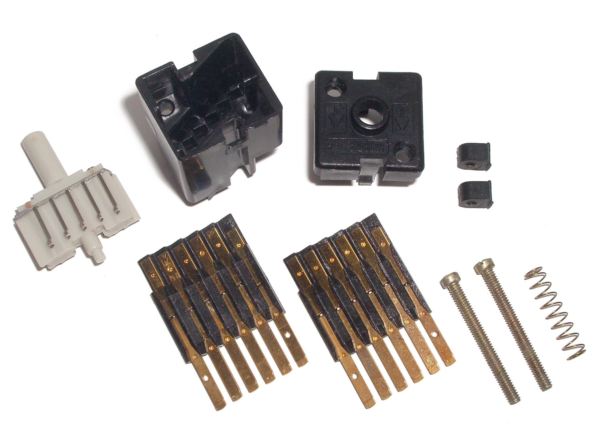
Several manufacturers advertised encoding switches: switches where the output code was set directly within each switch using individual electrical connections onto a common bus. Such switches required either multiple sets of switch contacts (one per output bit) or a single set of contacts divided into separate connections protected by diodes. Micro Switch’s KB range of switches started out around 1965 as an encoding system before the better-known reed switches were added to the range a year or two later. Micro Switch chose to use multiple contacts per switch; the output was configured by clipping off each terminal that was to represent a 0.
Mechanical Enterprises Mercutronic coding (MC) switches, first advertised in 1970, used diodes within each switch to link to a ribbon cable bus, a diode setting a 1 and no diode setting a 0. Other manufacturers who designed encoding switches around the turn of the 1970s included Magsat, IKOR (with their selective-shield capacitive system) and Synergistics. While surplus Micro Switch KB encoding switches are available to purchase, to date not a single encoding keyboard has ever been seen.
Although Licon and Cortron “magnetic valve” matrix scan keyboards are well-known, far less is seen of the very early keyboards from NAVCOR (1968) and Licon (1969) which used specific routing of wires through ferrite cores to define the output codes of the keys. Licon used an automated assembly line to feed wires through ferrite cores within the switches of their Series 550 keyboards (for example model 55-000084), while NAVCOR used ferrite core encoding in conjunction with reed switches.
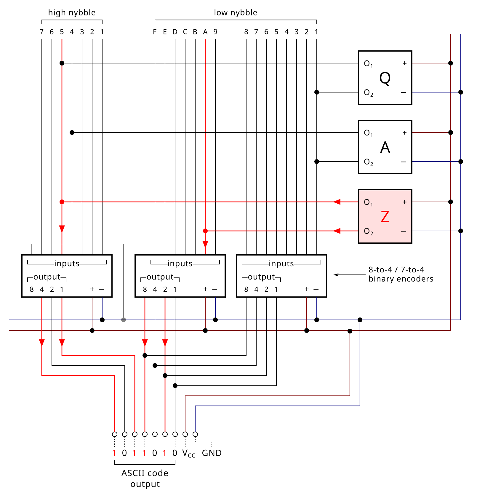
Why do all old Hall effect switches have four terminals? Why not merely three: VCC, GND and output? It’s not, as was originally suspected, for redundancy. Instead, it’s for the encoding. The two outputs from an active key form a 2-of-N constant weight code: a binary scheme where there is always a specific number of 1s set. The two outputs on a switch set exactly two encoder output bits as 1, leaving all other bits as 0. Each switch is still individually wired, and the early versions still required a dedicated PCB for the encoding grid (as with model 64SW1-4 from 1970), but the grid only requires simple links between the rows and columns, not diodes as with a diode matrix keyboard. The two outputs from the active switch are fed into a bank of binary encoder chips via the encoding grid to produce the output codes.
This technique is most associated with Micro Switch’s SW and SD Hall effect keyboards (and some early Hall effect keyboards from other brands) but it has also been found in a NASA keyboard made by Bendix using mechanical switches.
Encoding and rollover
These early techniques all had a particular limitation in common: pressing two keys at once would result in a clash. Pressing two light beam shutters at once would result in an invalid code. Pressing two keys on a shared bus likewise registers an invalid output. Pressing two keys in a 2-of-N keyboard would result in more than two inputs reaching the encoder.
In the 1960s some manufacturers opted for mechanical interlocking, where the operator was physically prevented from pressing two keys at once (or from pressing a key when the equipment was not ready to accept input). The amount of active keys can also be detected electronically. Depending on the encoder implementation, each key or each 2-of-N output line is fed into a special circuit through a resistor. By the law of parallel resistance, this circuit knows when exactly one key is pressed simply by looking for a specific amount of resistance in effect.
During rollover conditions, the keyboard detects the clash and goes inactive. When the first key is released, the clash ends and the second key can then be reported. Rollover involving three or more keys can result in the intermediate keys being dropped entirely as there is no point in time where they can be detected in isolation.
Micro Switch are believed to have invented the term “N-key rollover”, a concept where rollover is no longer an issue. Their approach took the form of switches that instantly deactivate upon actuation, taking themselves out of the equation. No matter how long a key is held for, it will register only momentarily. While both Micro Switch and TEC made mechanical self-deactivating switches and Cherry filed a patent for such a switch, it is Micro Switch’s sink pulse Hall effect switches that are widely encountered in their N-key rollover keyboards.
Self-deactivation was acceptable in the 1970s because of how keyboards of the day worked. Historically, keyboards reported the output code directly. ASCII keyboards were common; these keyboards transmitted ASCII codes directly to the host equipment. Keyboards did not send make and break codes, so there was no way to know if a key was still held, and there was no reason to hold down two alphanumeric keys at once. Even repeat was handled differently, using either a Repeat key or (for special keys such as enter, space and backspace) keys designed to signal repeat. (Modifier keys of course did not self-deactivate!)
The implications of contact bounce
Contact bounce is well known by keyboard enthusiasts as chatter: where pressing a key unintentionally generates two more occurrences of the same letter on the screen. When switch contacts—be they gold-alloy prisms on sprung metal contacts or carbon-silver traces on polyester sheets—are pressed together, they rebound repeatedly for a brief fraction of a second. How long this bounce period lasts depends on the design of the switch and how much use the switch has seen. Standard metal-contact switches are typically rated to bounce for no longer than 5 milliseconds, this being one of the determinants of end-of-life condition (bounce time when new will be far less). Membrane switches are rated for up to 20 ms, while reed switches—whose contacts are lightweight and barely move—are rated for as low as 2 ms at end of life. Chatter occurs when the switch contacts continue to bounce outside of the expected tolerance, but all contact-based switches exhibit bounce even when new.
In the aforementioned encoding processes, keyboards were susceptible to bounce, so a means was required to prevent duplicate keystrokes. A wide and sometimes bizarre range of switch designs were introduced that were bounce-free, including capacitive and inductive types. Perhaps the strangest was Mechanical Enterprises’ three generations of Mercutronic mercury-contact switches (MC, SS and M-5), using a silicone rubber tube containing mercury that is pinched closed when the keys are at rest: using liquid metal switch contacts avoided bounce! Perhaps unsurprisingly, none of these mercury keyboards have ever knowingly resurfaced.
Optical and Hall effect switches were also bounce free, and although there is no longer any mainstream demand for that technology now for the purposes of reliability, the increased responsiveness owing to not needing to debounce the keys has led to their reintroduction to the market to meet gamers’ demands for the lowest possible latencies in their rigs.
Matrix scan
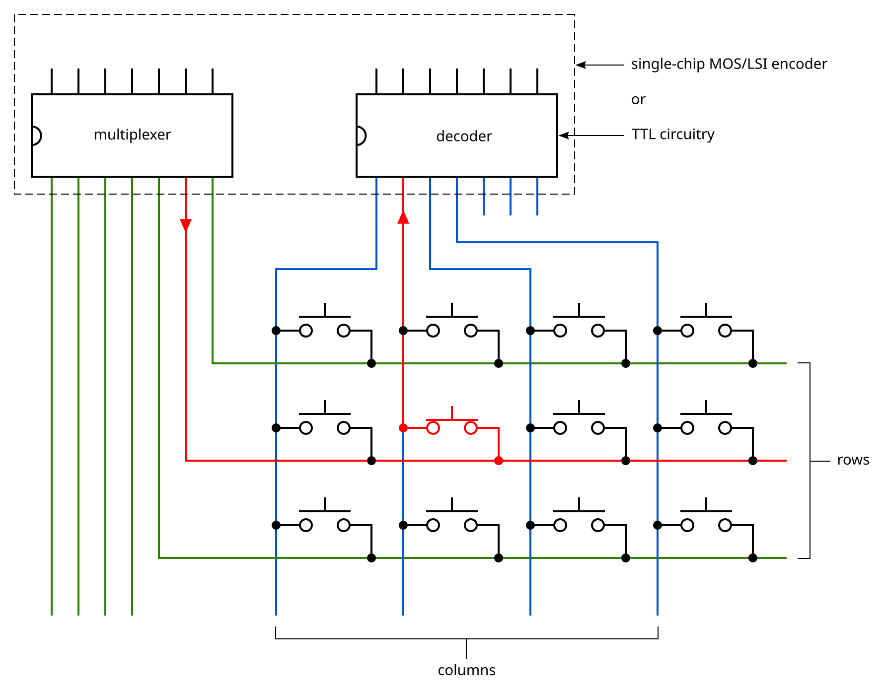
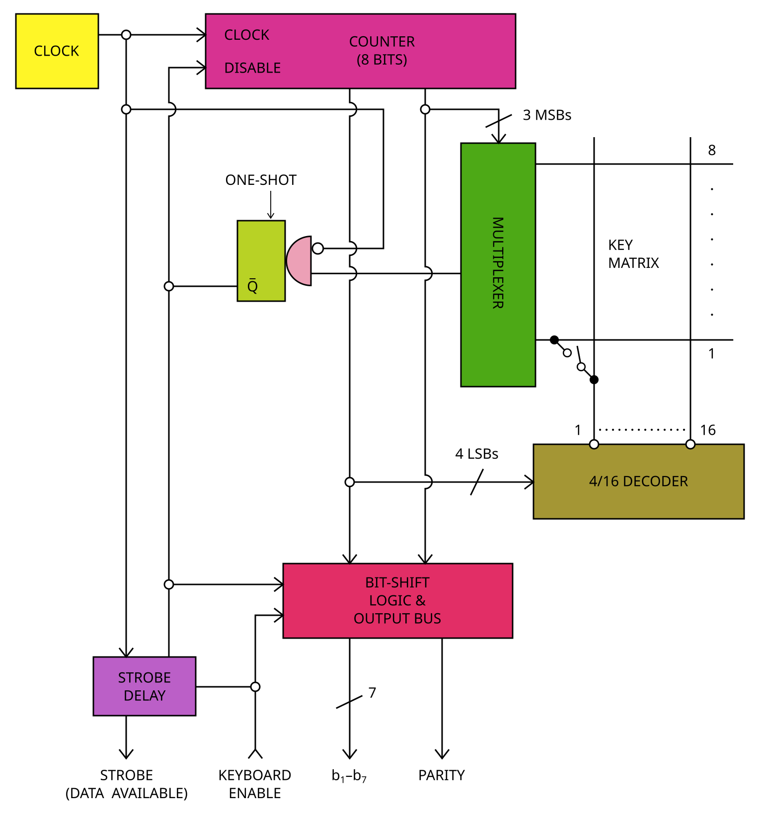
Matrix scan—the encoding technique in use in all keyboards today—appears to have arrived on the scene in 1970. Cherry and Clare-Pendar both advertised this technique in that year. Cherry’s approach was based on TTL—transistor-transistor logic—while Clare-Pendar put the entire encoder onto a single chip. A TTL-based encoder took somewhere in the region of 14 logic chips depending on the implementation.
In a matrix scan keyboard the switches are wired into a grid instead of separately as was the case up to this point. A timer-driven circuit tests each key in sequence to see if it has been pressed. Once a keypress is detected, the x and y co-ordinates of the key are used to identify it.
The advent of matrix scan solved some very important problems. Firstly, it made debounce trivial, opening the way to mass-market cost-effective metal contact (“mechanical”) keyboards. All the encoder circuit needed to do in order to debounce a key is pause the scanning process for a few milliseconds. If the switch is still registering after that delay, the encoder can be certain that it’s picking up a keypress and not a spike. All the innovative switch designs—too many to go into here—that were designed to combat contact bounce were rendered obsolete, and it would seem that many designed around this time simply disappeared off the market.
Secondly, matrix scan allowed the centralisation of the sensing logic. The complexities of inductive and capacitive sensing could be moved to a single circuit shared by all the keys, removing the need for dedicated circuitry or wiring at each key.
Thirdly, matrix scan makes encoding very easy. The matrix co-ordinates for each switch can be fed into a look-up table in ROM. TTL-based encoders had to use the matrix co-ordinates directly as the output code, meaning that repositioning keys (e.g. QWERTY vs AZERTY) required a new PCB layout, but MOS/LSI encoders simply needed replacement ROM data.
Finally, matrix scan allows for the unlimited rollover that gamers demand today. Unlike Micro Switch’s N-key rollover technique, matrix scan keyboards not only allow for an unlimited number of overlapping keystrokes, but they can correctly identify each and every simultaneously-held key, a feat impossible up to this point.
The removal of the encoding bus means that there is no encoding clash during rollover conditions. Matrix scan did introduce a clash of its own: ghosting. However, capacitive switches are immune to ghosting and mechanical switches need only a diode at each key position to prevent it. Even without diodes, any two keys can be held at once and remain independently detected.
DTL, TTL and MOS/LSI
Early encoding techniques that involved logic circuitry were built on DTL (diode–transistor logic) and TTL (transistor–transistor logic). These are simple chips that provide the building blocks of a logic system, such as a set of six NOT gates (a “hex inverter”), four NAND gates (“quad NAND”) or a binary counter on a single chip, most commonly a DIP-14 package.
Around 1970, the single-chip encoder was introduced. This is an entire keyboard encoder circuit—minus the timing resistor and capacitor—on a single chip. Such chips are of the LSI (large-scale integration) type, also known as MOS based on the type of transistors used inside. Various companies supplied single-chip keyboard encoders, with National Semiconductor, General Instrument and SMC being the most commonly encountered. The look-up table from the matrix to the output codes was typically stored inside the chip. ASCII encoders provided ASCII output. “PRO” encoders simply output a memory address to be used with a separate look-up table ROM, important for small custom batches and for prototyping. Each key would have three or four separately-defined outputs that were selected according to whether Control or Shift or both was held.
It’s likely that many of the MOS/LSI encoders on 70s and early 80s keyboards have been mistaken for “controllers” (microprocessor-based encoders) but they are fairly simple single-chip circuits.
Microprocessor encoders
Only by 1977 was it finally deemed viable to dedicate a simple microprocessor to scanning a keyboard. Two such keyboards—so-called “intelligent” keyboards at the time—were introduced in that year: IMSAI’s IKB-1 and Micro Switch’s SD series 103SD24-1.
With microprocessor-encoded keyboards, the entire encoding process is handled by firmware stored in ROM on the chip. Changes to the encoding behaviour can be made in the firmware code without needing to redesign the encoder circuit. With MOS/LSI encoders, a change as simple as adding Caps Lock (versus the industry-standard Shift Lock) required additional logic circuitry to manipulate the output code. Now, only firmware in ROM needed to be changed.
This comparatively expensive approach would not become standard overnight. This approach was for example too expensive for home computers in the 80s with their built-in keyboards. Apple favoured MOS encoders, while Acorn put only simple logic onto the BBC Microcomputer’s keyboard PCB and the remainder of the encoding process into the operating system.
The IBM Personal Computer did use a microprocessor-driven keyboard, based on an Intel 8048 chip from their popular MCS-48 family of microcontrollers.
This approach grew in popularity, with keyboards using both general purpose microcontrollers and dedicated microcontroller-based encoders from a variety of brands including Intel (MCS-48 and MCS-51 families), Zilog and Fujitsu and now the likes of Holtek. Matrix scan using microprocessor-based encoders became the industry standard.
Credits
Much of the research on which this article is based was made possible through the hard work and dedication of archivists Bitsavers and World Radio History and material held at the Internet Archive. This material contains not just old articles but also a huge number of historical product advertisements in magazines that help piece the story together. Research into Micro Switch’s Hall effect keyboards and their encoding system was also assisted by Trina Brown, head librarian at the National Museum of American History Library.
Daniel Beardsmore (42) | |
| Location | Hertfordshire, United Kingdom |
| Occupation | IT |
| Joined | 2009 |
| Niche | Keyboard industry history |
| Fav. switch | ITT ETL18, Omron B2H |
| Other hobbies | UK high voltage transmission towers, walk photography |
| Links | Telcontar.net, imgur.com/user/thatpylonguy |
Published on Fri 8th Dec 2023. Featured in KBD #2023.

