Keyboard Builders' Digest / Advent Calendar
Keyboard Case Design
Sadek Baroudi provides a detailed walkthrough of how he designs 3D models – Starting with a PCB, and ending with a model that you can export for 3D printing.

Published December 11, 2022
Overview
In this guide, I'll be providing an detailed walkthrough of how I design 3D models for cases, with the intent of 3D printing them. This starts with a completed keyboard pcb from the kicad files, and ends with a fusion 360 model that you can export as an stl/3mf for 3D printing. For this guide, I'll be using the chocolad as an example. As of writing this sentence, I haven't designed the case yet!
https://github.com/jimmerricks/chocolad
Prerequisites
- You have a basic understanding of kicad
- You have inkscape installed (only used to convert svg to dxf in a way that fusion 360 can consume)
- You have fusion 360 installed
Follow along
I have included the kicad_pcb file used in this example. So, if you'd like to follow along with the instructions below, you can create the same exact case I did! I find that it's a good way to validate what you're reading, and gives you experience for the next case you make.
Navigate to the src directory to see the files.
Walkthrough
Kicad
Kicad is a perfect place to start, as it provides you with exact dimensions to create a case. This includes, but is not limited to:
- PCB outline
- Switch locations
- Reset switch location
- On/off switch location (for wireless builds)
- Controller location and dimensions
- Rotary encoders
- OLED
- etc
---
PCB footprints
So, let's first look at the pcb to make sure it has everything we need to consider when doing the initial sketch for the case. You'll want to hide the copper layers so you can clearly see the pcb and footprints to identify what you care about for the case.

---
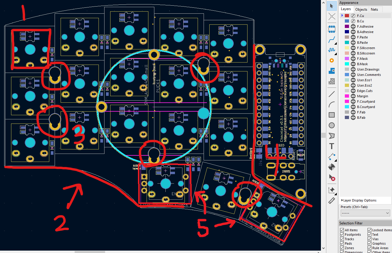
Case considerations
There are 5 considerations when looking at this particular PCB:
- The keyswitch cutouts
- The edge cuts of the pcb
- The mounting holes for the M2 standoffs
- The opening for the controller, trrs, reset switch
- The EC11 encoders
(Optional) Also note that there are 4 mounting holes for the tenting puck, which I did not include in the screen shot.
---
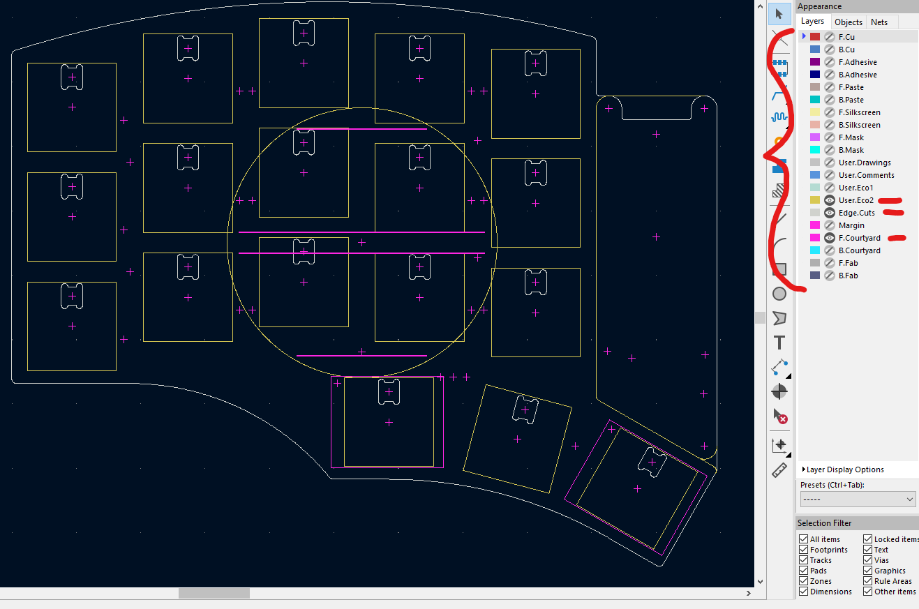
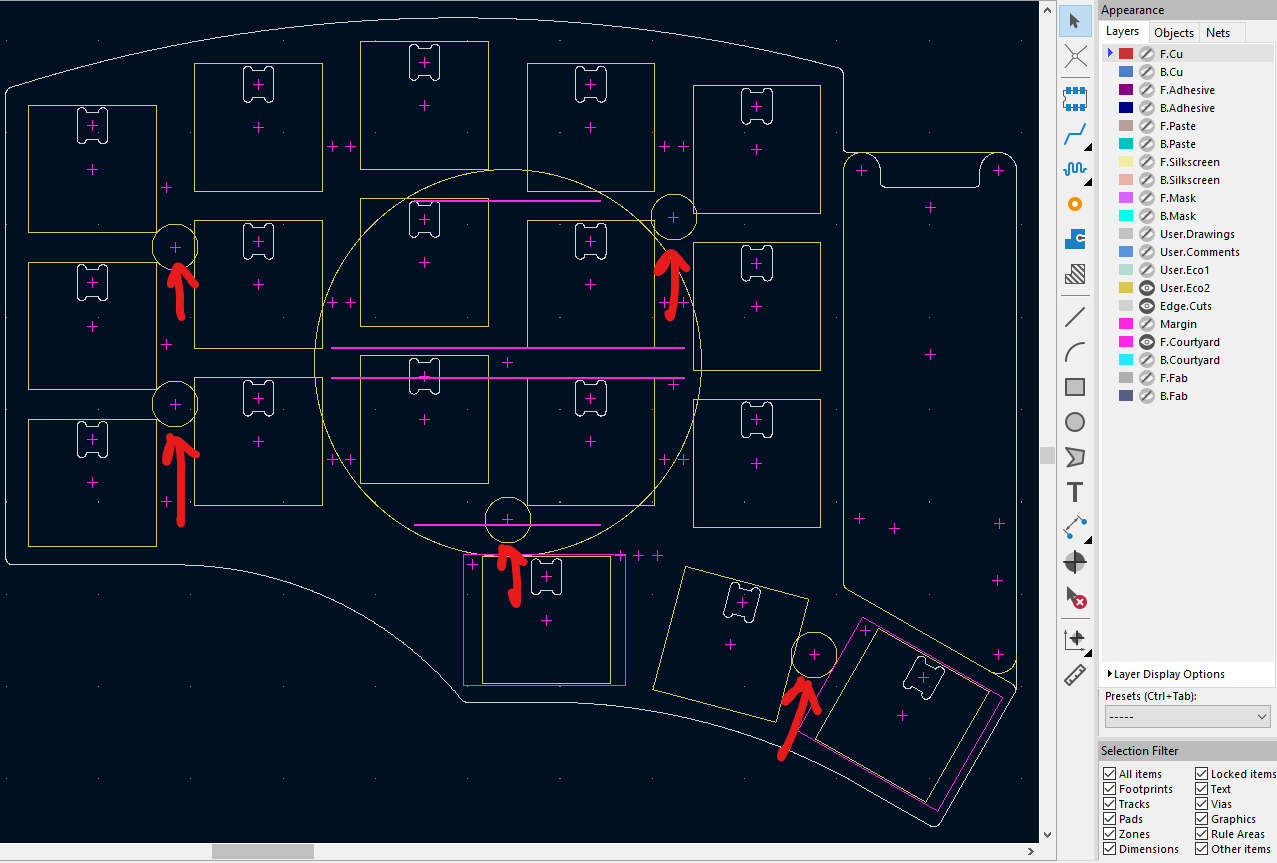
Deselect layers
At this point, you want to deselect layers until you have everything you need, while keeping as little showing as possible otherwise. In this case, User.Eco2, Edge.Cuts, and F.Courtyard leaves us with almost everything. The only thing missing is the mounting holes.
---
Update footprints
There was no good layer to expose the mounting holes without exposing way too much from the pcb. It's important not to expose to much, because we'll be exporting this as an SVG. By leaving too much, you have to do a lot more cleanup in SVG later. This is a tedious process, so let's add some drawings to the mounting hole footprints using one of the layers that we've identified in a previous step.
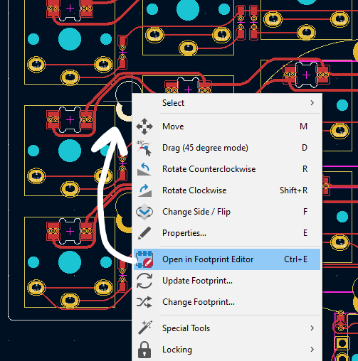
So, here we edit the footprint and add a circle centered around the mounting hole on the User.Eco2 layer, since we're exporting that already. Do this for each of the mounting holes.
(Optional) As noted earlier, you could follow the same process for the tenting puck mounting holes, and include them in the bottom plate. This would allow you to mount a tenting puck to the bottom plate of the case.

---
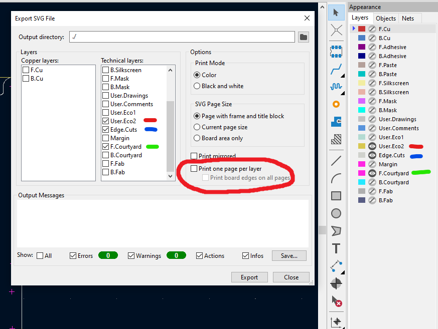
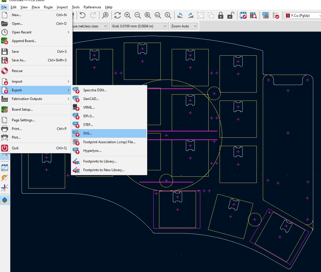
Export SVG
Now, we export an SVG and include only the layers we identified earlier.
---
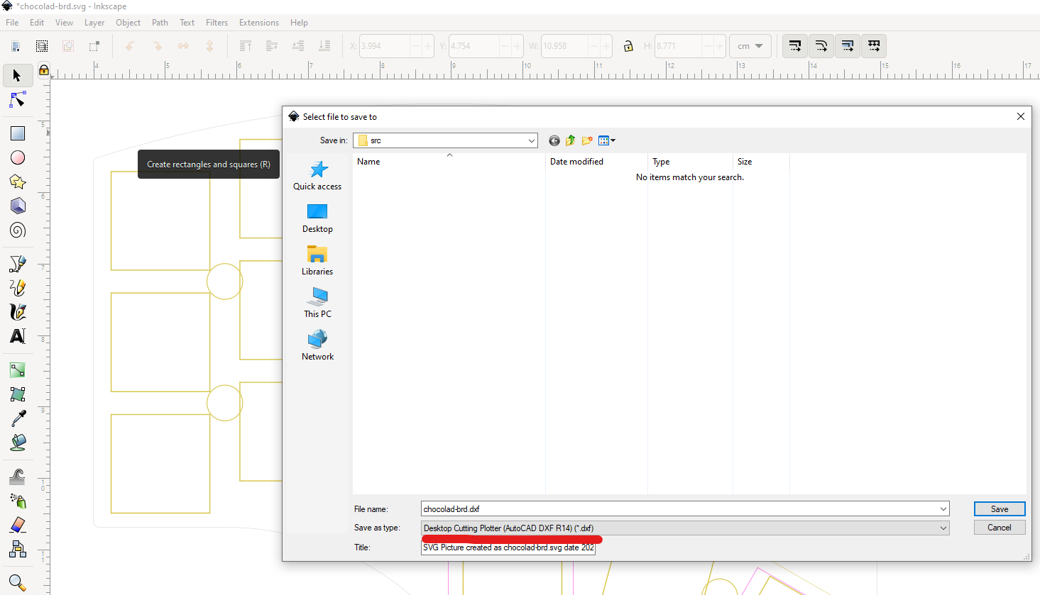
Save as DXF
You don't have to use Inkscape, but I've found that Inkscape is very reliable in giving us a usable DXF file for Fusion 360. Use the R14 format, and make sure it's set to mm as the unit.
---
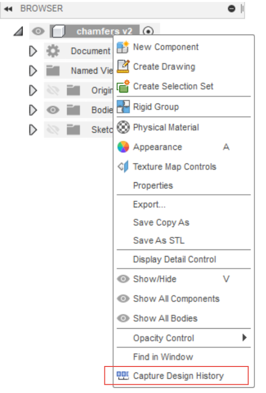
Enable capture design history
If you already use Fusion 360, you may already have this enabled, but if you don't, it's really good to enable this before you get started. Otherwise, it will be hard to make adjustments later!
---
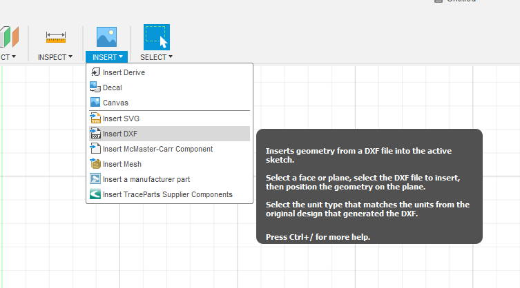
Import DXF into Fusion 360
Now we go into Fusion 360 and import the DXF we just saved from Inkscape.
---
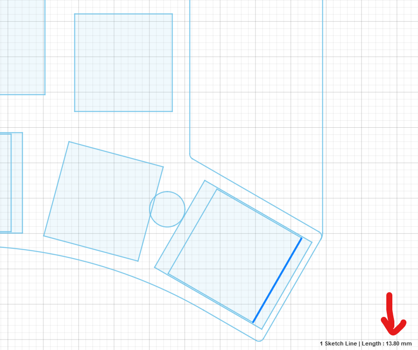
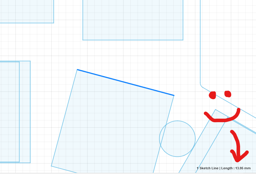
Check switch hole size
Check the size of the switch holes. For choc switches, they should be 13.95mm. For MX switches, 14mm works great. If you are doing this for a pcb that supports both choc and MX, 14mm is fine. It feels a bit loose for choc switches, but it'll still work fine.
---
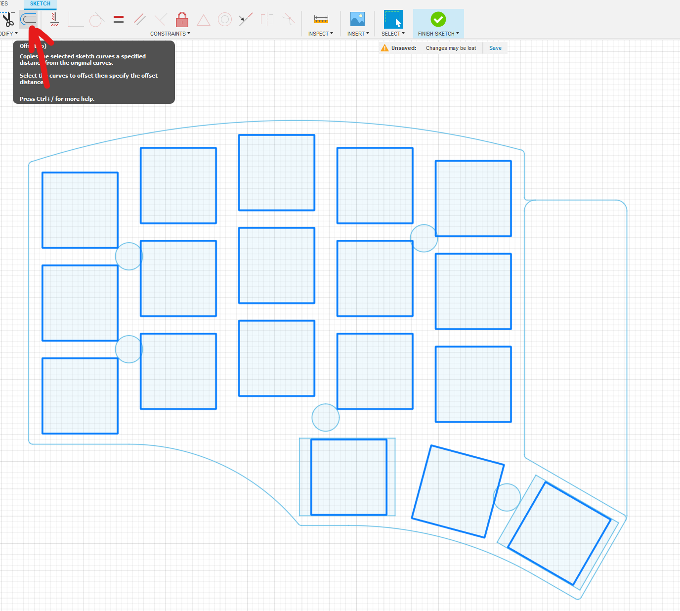
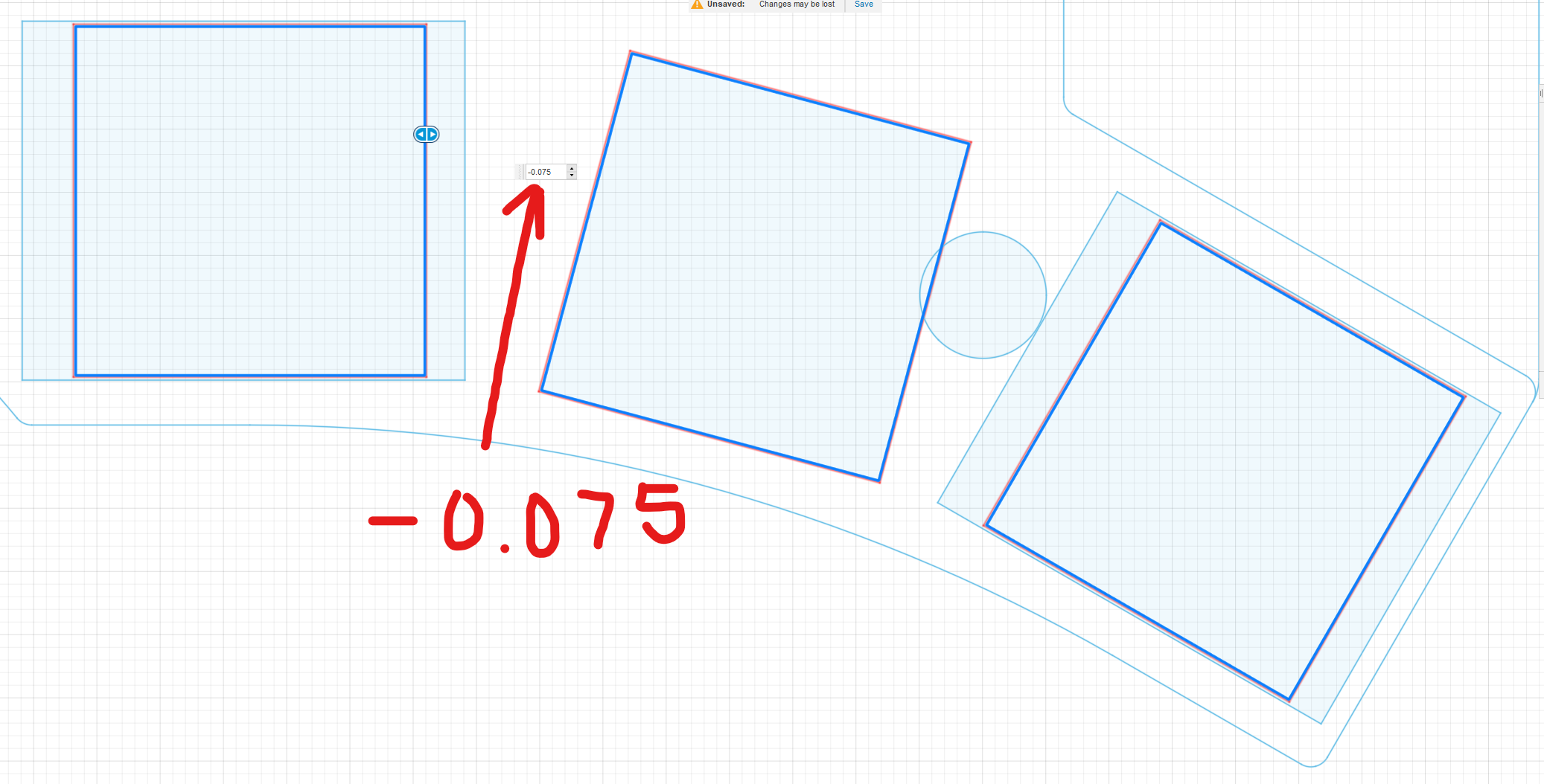
Adjust switch holes size
If they are not correct, select all the switch holes, and offset them by whatever distance you need to make them 13.95mm or 14mm.
---
Switch hole size confirmation
Now confirm that the switch holes are correct!
---
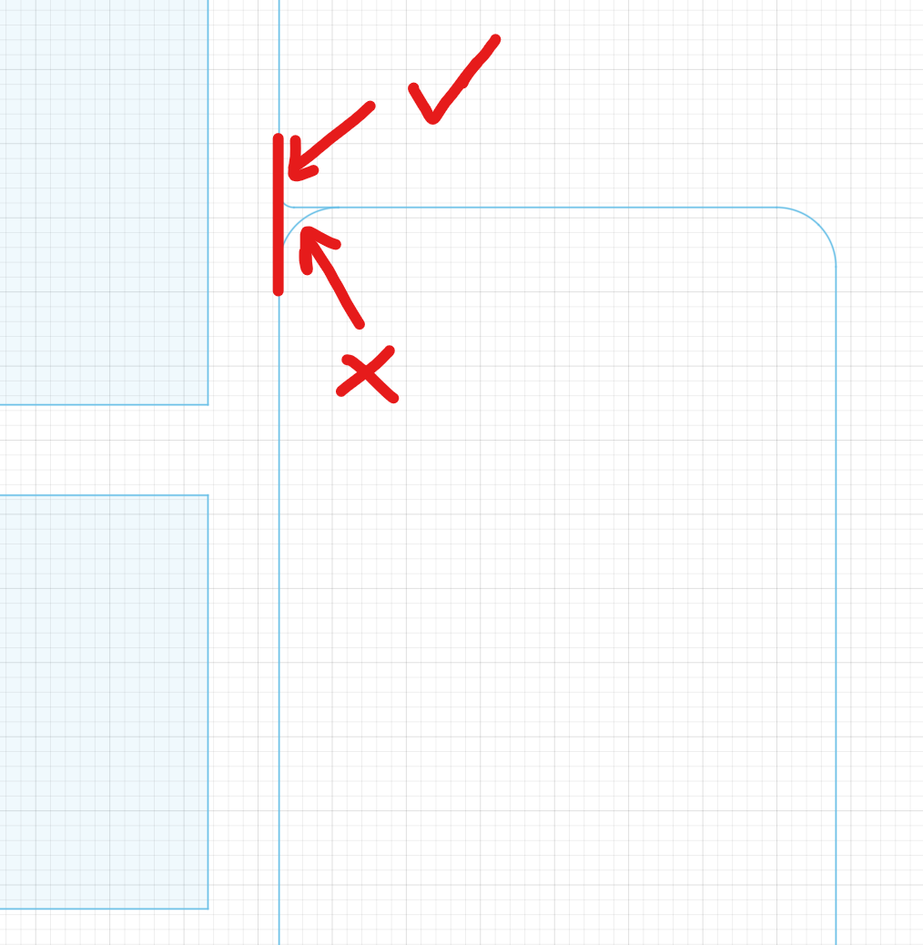
Fix edges
Look around the perimeter of the board and make sure it's a continuous shape. If you see anything that needs some adjustment, fix it in the sketch. In this case, there is an extra curve that we don't want, so let's remove that and make it a straight line.
---
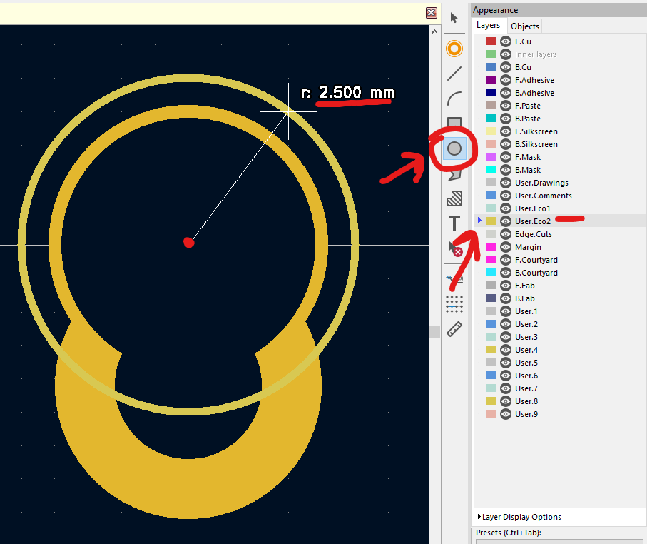
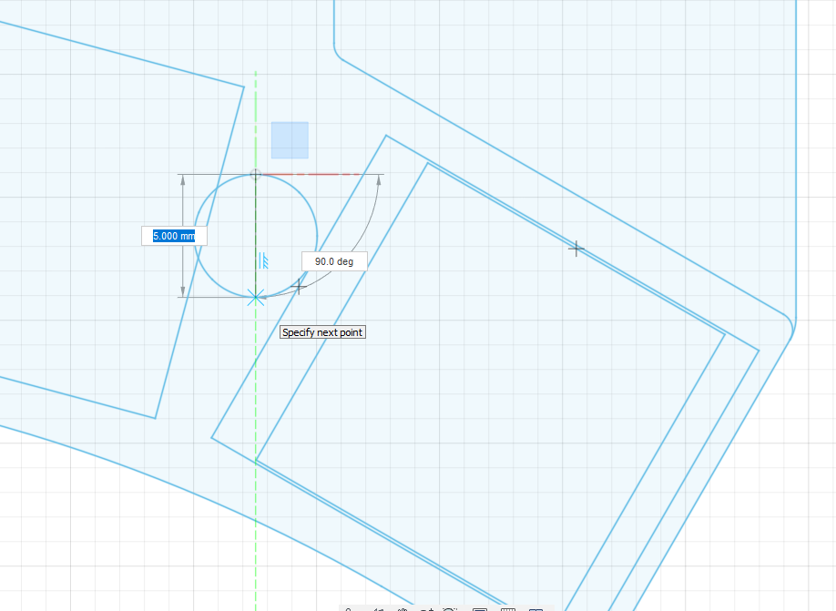
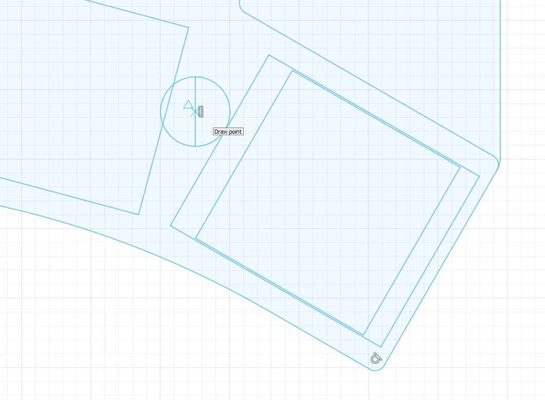
Mounting hole cleanup
Now we need to adjust the mounting hole size to be correct. Most boards use M2 standoffs, so the hole for the screws here should have a diameter of 2.5mm. Draw a line down the center to identify the center point. Then place a point in the center. Once you do that, you can delete the existing circle and line.
---
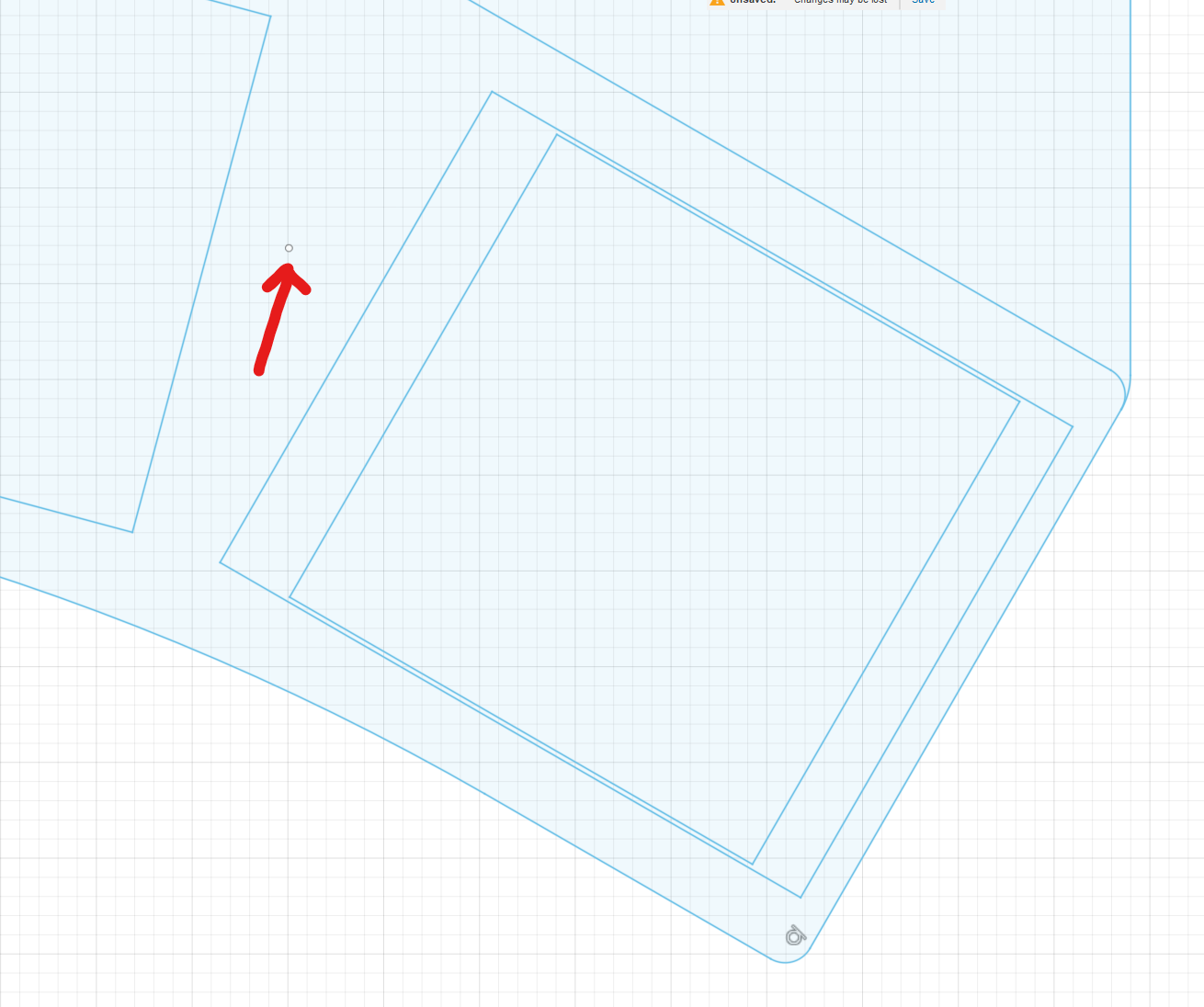
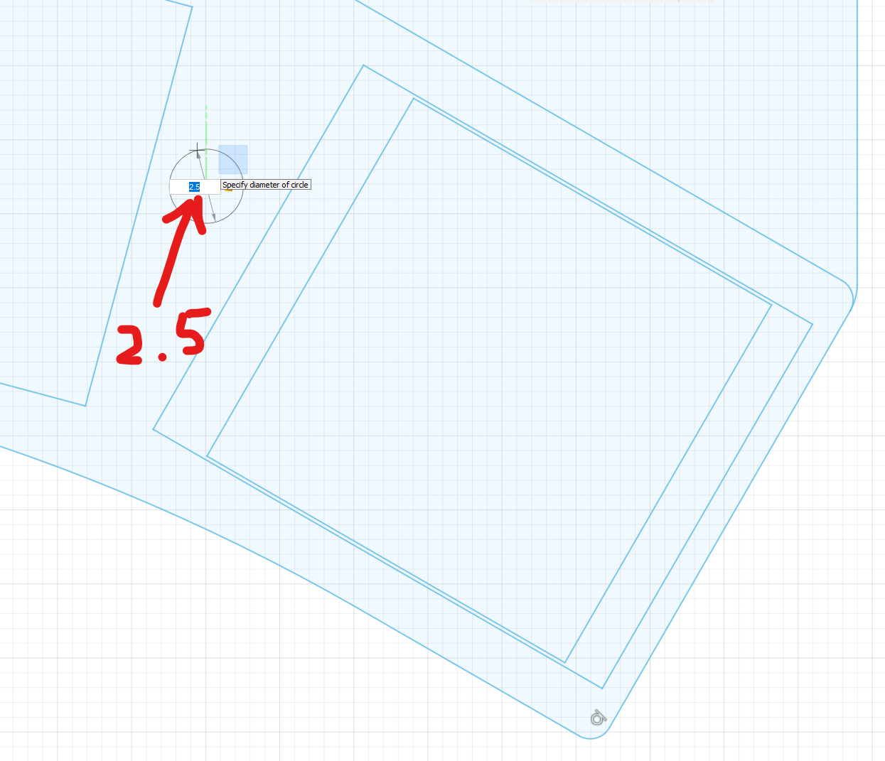
Create new mounting holes
Now that you have a point, draw a center circle around that point, with a diameter of 2.5mm. Repeat this for all of the mounting holes on the board.
---
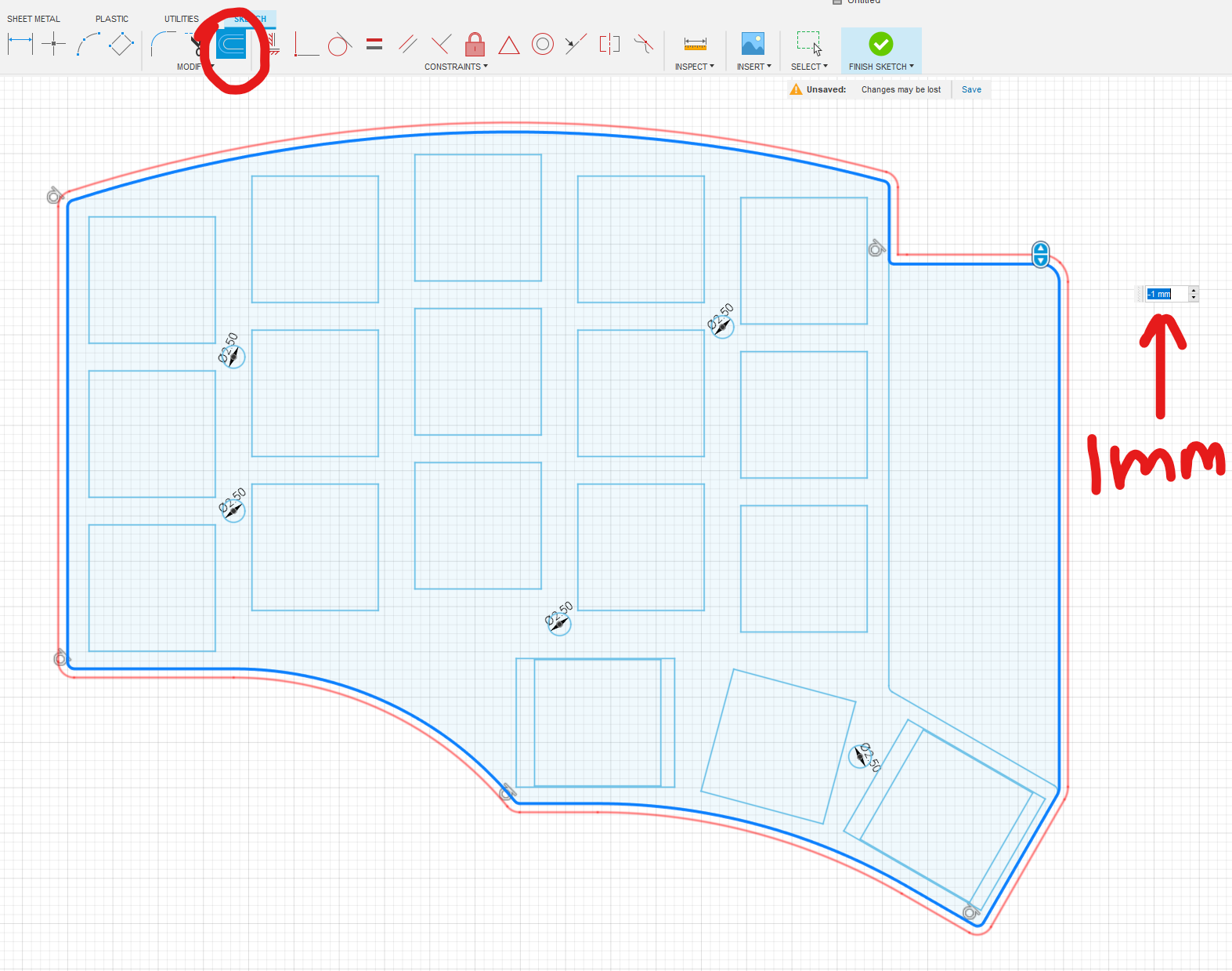
Case outline offsets
At this point, we want to select the perimeter of the case, and offset it by about 1mm. If you don't do this, the pcb may not fit in the case, as you want to leave room for error from the PCB manufacturing process.
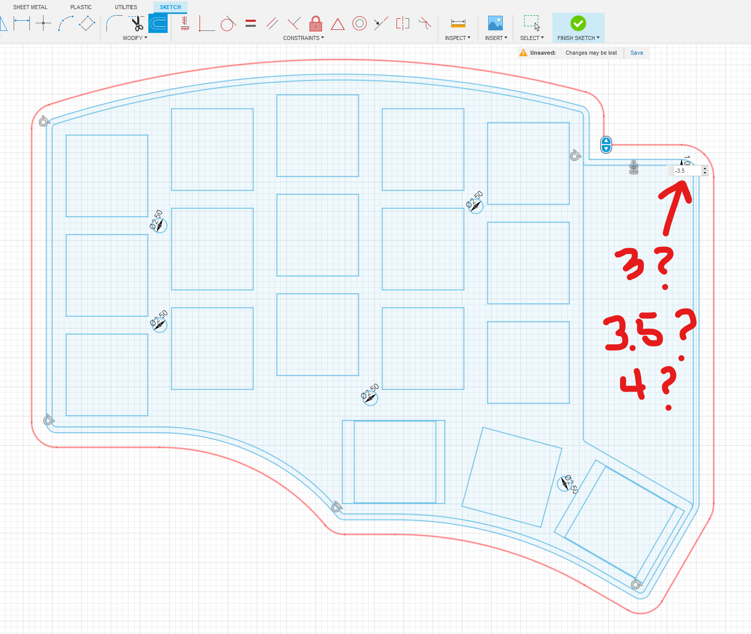
In the last step, we created the case inner wall. Now we need to create the outer wall. You should do the same exact thing you did in the previous step, but increase the offset value. If you want a 2mm thick wall in your case, select 3mm. If you want larger, increase the value as much as you like!
---
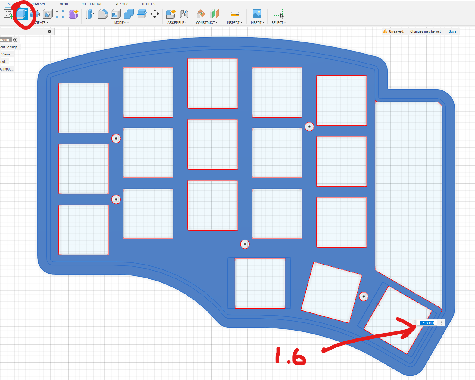
Switch plate extrude
At this point, we want to extrude the plate. You should select everything but the switch holes, mounting holes, and any other area that protrudes above the switch plate. In this case, we want to exclude the region that has the controller, TRRS, and reset switch. This should generally be a thickness of 1.6mm. You can go thicker, but I don't recommend going higher than 2mm.
---
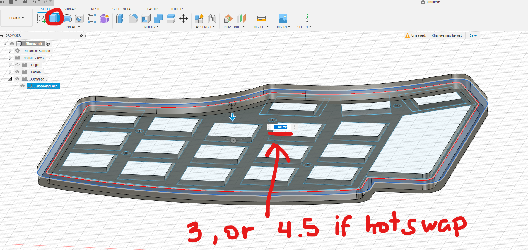
Wall extrude
Now you want to extrude the walls in the region we offset earlier. The height of this is very important. You don't want to go too short, but you don't want to go much taller than you need. My general rule of thumb is:
- For choc switches, 3mm if soldered, and 4.5mm if hotswap
- For MX switches, 6.5mm if soldered, 8mm if hotswap
You can experiment with values until you get what you're looking for.
---
Add style and texture
I usually like to add some texture to the outline, but this is a stylistic preference, so feel free to adapt it, or skip this step if you don't mind the sharp edges.

---
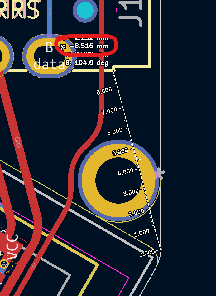
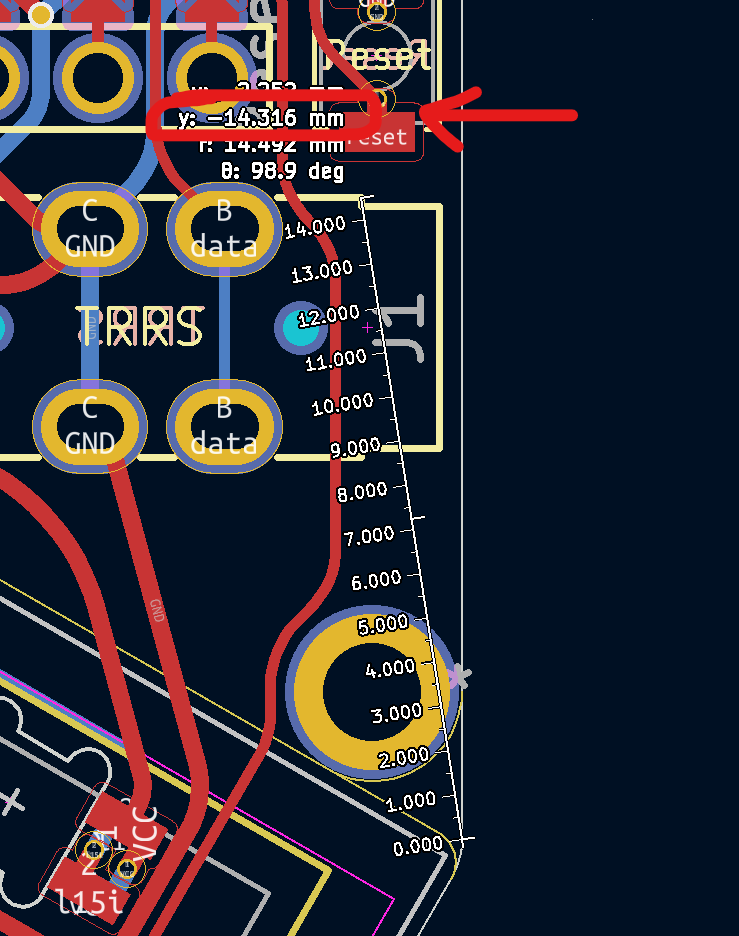
Adjust for other components (measure and draw)
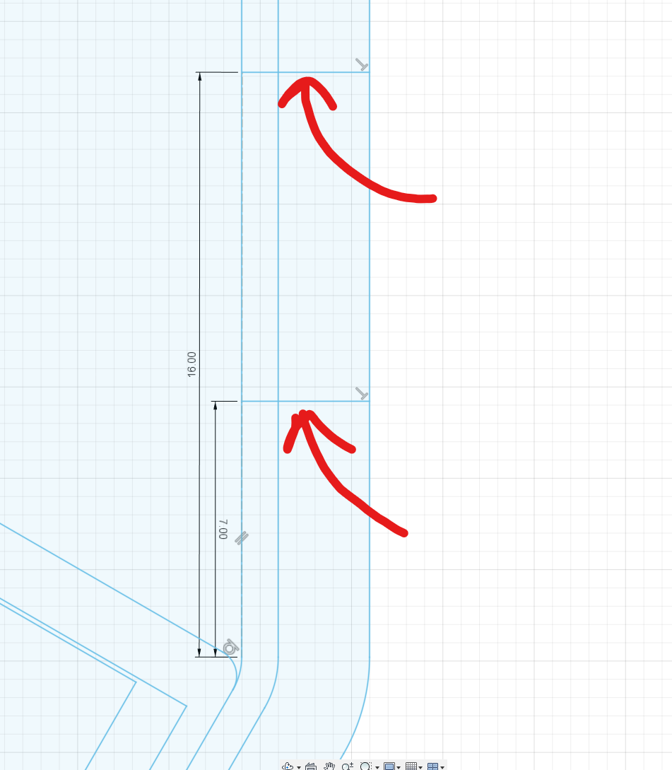
So, admittedly, I forgot to account for the depth of the trrs cable in the case. That said, this actually serves as a great example to illustrate how to solve for it. I measure from a known point on the pcb outline, and look at the Y values (in this case). I check to the bottom edge of the TRRS port, and the top edge of the TRRS port. Then I offset by a couple of mm or so to make sure there is enough clearance for the TRRS cable end.
---
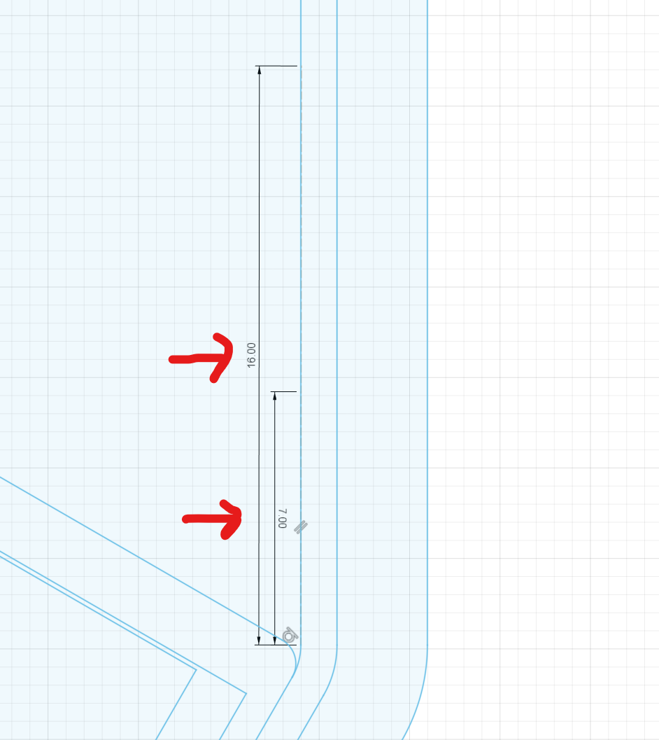
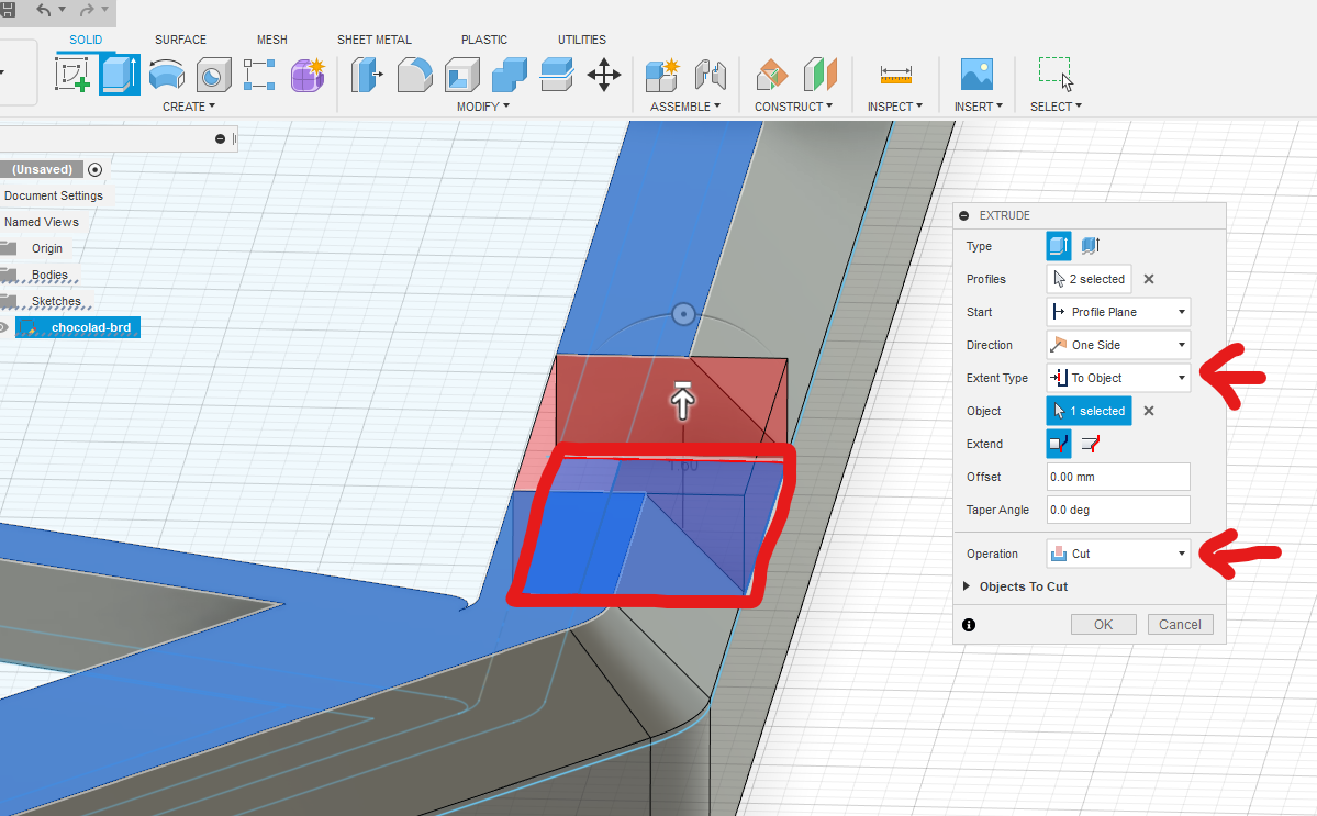
Adjust for other components (extrude)
Now that we have drawn the lines and created a region to extrude, we extrude down to give room to plug in the cable.
---
Create the bottom plate sketch
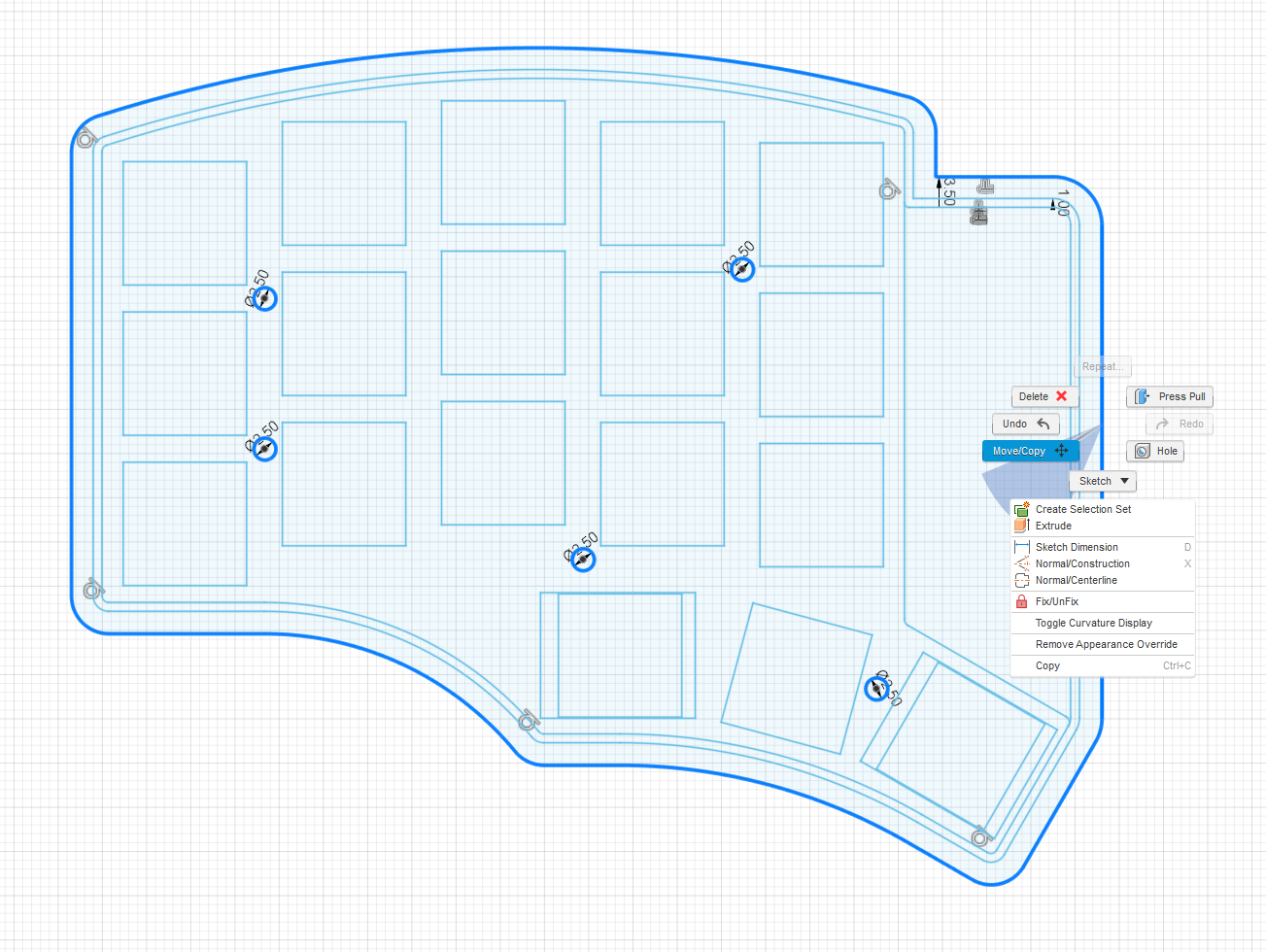
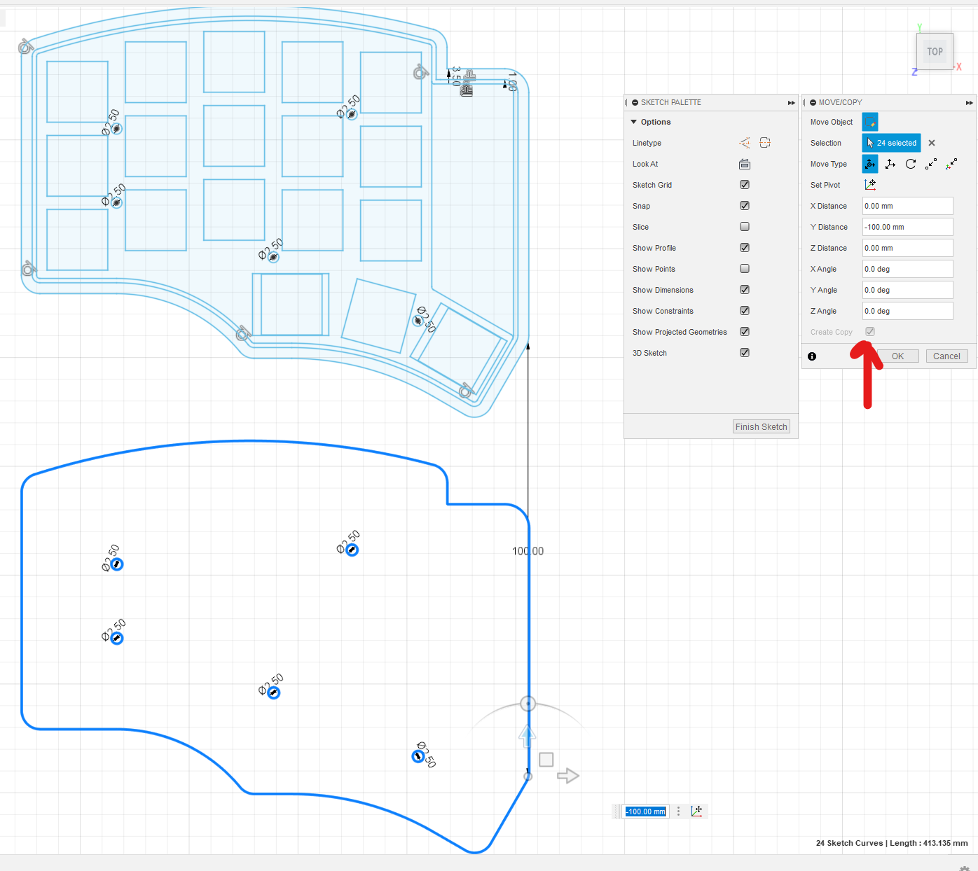
Last step is to create the bottom plate, which you will use to screw in to the body using the mounting holes. This part is very easy! You go back and edit the original sketch. Then you copy the border of the case and the mounting holes.
---
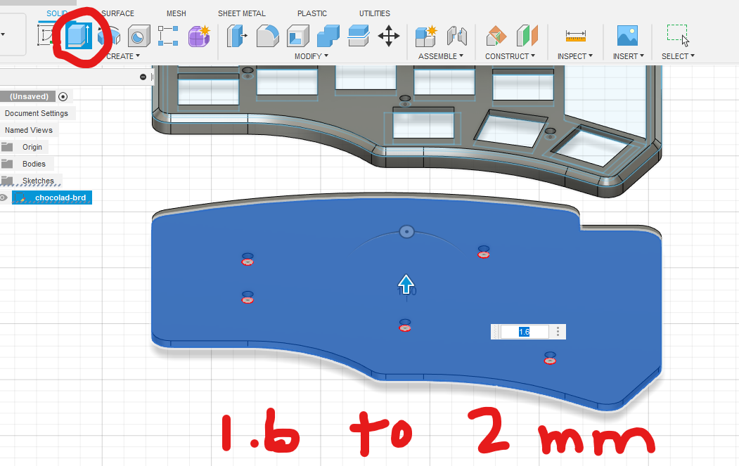
Extrude the bottom plate
Once you have the plate sketch, you extrude by whatever thickness you like (2mm is a very good sweet spot, but I sometimes do 1.6 for a slighly lower profile keyboard)
---
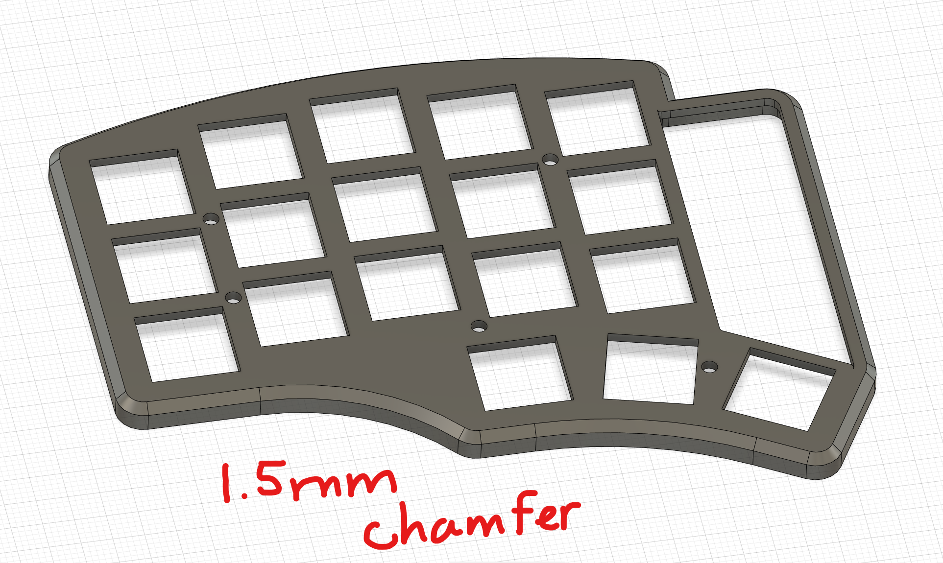
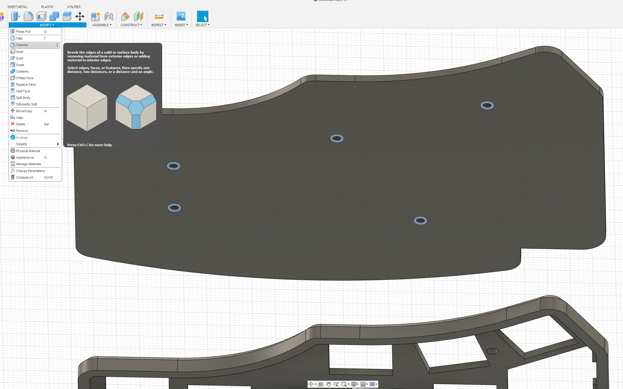
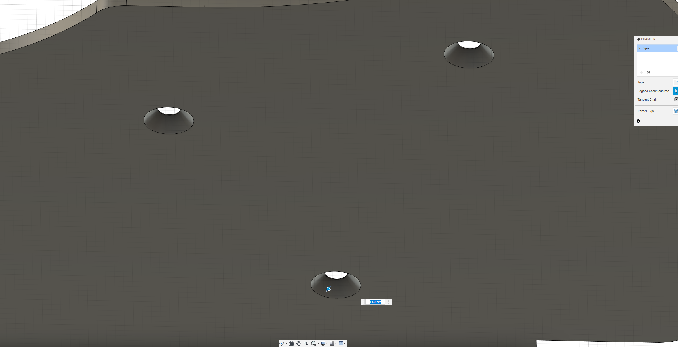
Chamfer mounting holes (optional)
If you are using countersunk screws, you can optionally decide to chamfer the mounting to help accommodate that. It helps to create a flush bottom plate. I generally consider this unnecessary, since you will usually use bump ons, which protrude farther than M2 screw heads. But if you'd like to experiment with this, see the images below as an example. The example is using a 1.6mm bottom plate, which I generally wouldn't recommend if doing this. I'd suggest using at least a 2mm thickness bottom plate.
---
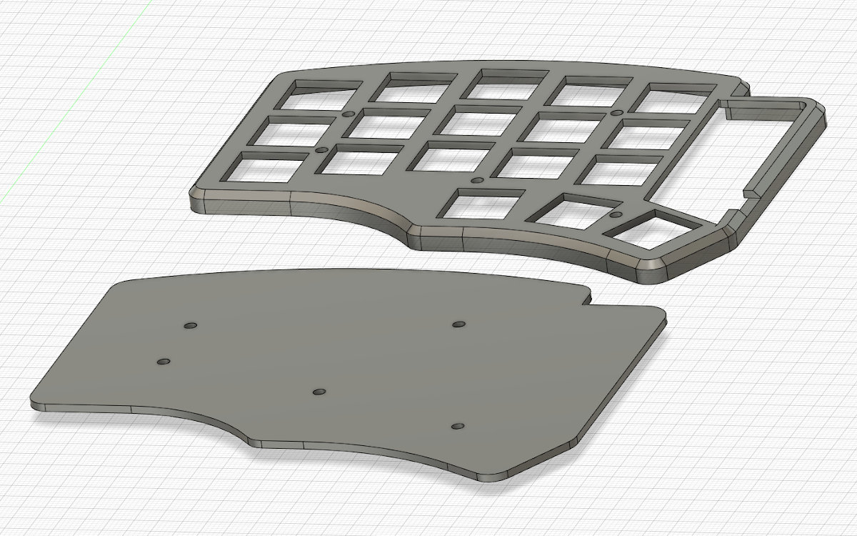
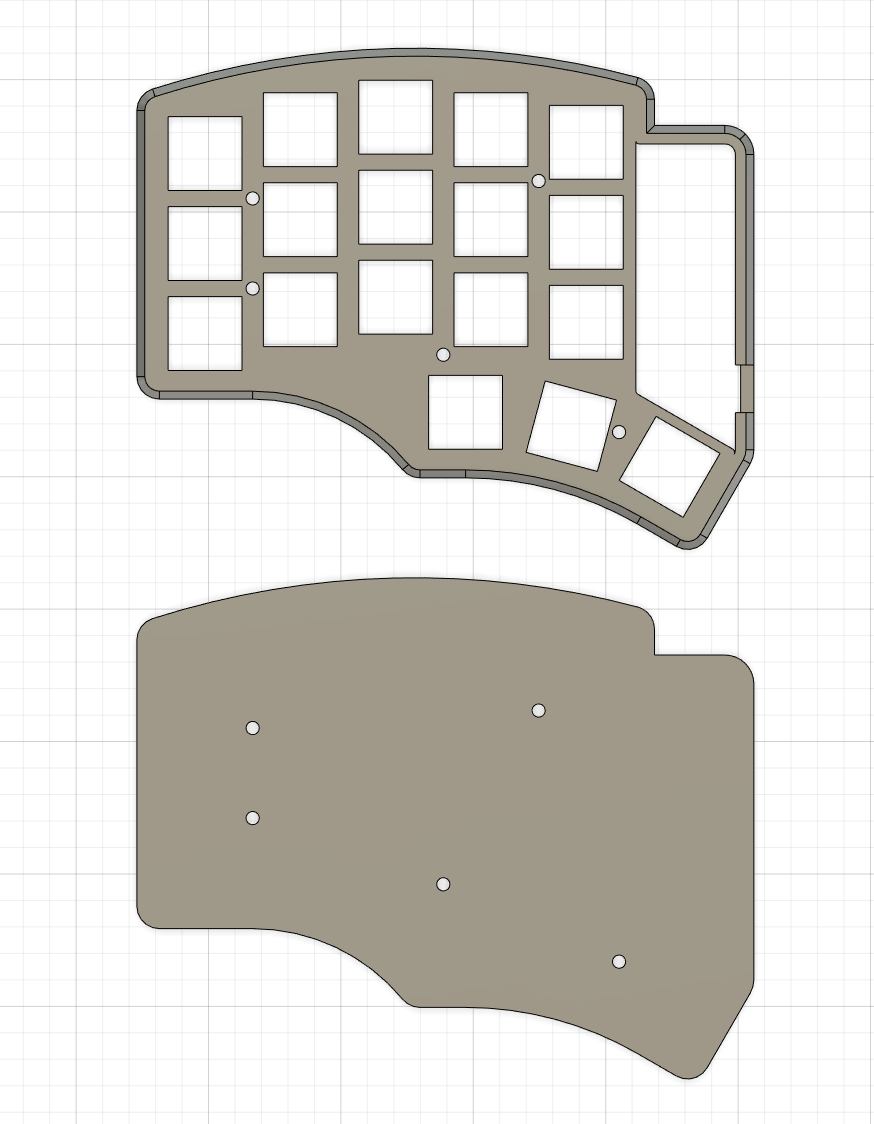
Complete case
You are done! Export this as an stl, print it, and do a test fit. If you need to make adjustments, you already know all the steps above. Go back into Fusion 360 and edit using the timeline.

Resources
 | Sadek Baroudisadekbaroudi, sadekbaroudi#1258 |
|---|---|
| Location | California, USA |
| Description | Got into ergo mech, started designing, fell in love, never looked back |
| Joined | 2020 |
| Niche | Unibody splits |
| Fav. switch | Momoka Frog v3s, Gateron Red Ink V2s, Gateron KS-3 Milky Yellow Pros |
| Fav. keycap profile | MT3, DES |
| Links | https://fingerpunch.xyz/, https://github.com/sadekbaroudi, https://fingerpunch.xyz/discord, https://reddit.com/u/sadekbaroudi, https://instagram.com/fingerpunchkb |
Published on Sun 11th Dec 2022. Featured in KBD #107.
Related

Lattice60
PrimeNumber shared the files of the handwired Lattice60, an ortholinear keyboard with standard keycaps and low-poly case.
QMK RGB Matrix configuration
The focus of Sadek Baroudi's tutorial is how to properly configure RGB Matrix especially for non-trivial ergo keyboards with angles and column stagger.
How to organize a keyboard meetup
Gordon Diggs, the man behind the NYC Mechanical Keyboard Meetups, gives us some tips on how to organize a meetup.
Building keyboards with lasers
Ming-Gih Lam walks through the process of how to build keyboard cases using vector graphics software and a laser cutter.