Keyboard Builders' Digest / Advent Calendar
Designing for Wireless
Pete Johanson, keyboard designer and creator/project lead of the ZMK firmware, offers some guidance for keyboard designers new to wireless designs.

Published December 7, 2022
Pete Johanson has been toiling away on ZMK since he first got annoyed by the wires on his split and decided it was time to do something about it. He's been leading the project since it's start in early 2020, and recently did the crazy thing and quit his day job to focus on family and ZMK/keyboards.
---
Many of the core concepts covered in excellent existing guides like the ai03 keyboard guide offer fundamental concepts needed to design and create wired keyboards. However, with the increase in availability of wireless controllers like the nice!nano and Seeed XIAO BLE, and firmware options like ZMK, there are additional design guidelines that can help designers to create power and RF efficient keyboards.
Before diving in, I would like to acknowledge all of the amazing folks who have helped me learn all this along the way. I do not come from an EE/embedded/hardware background, so I am only able to share this thanks to the knowledge others have shared with me.
Power Efficiency
Wireless keyboards spend the majority of their time powered by a battery (typically rechargeable LiPo). Unlike wired keyboards, which have an effectively limitless supply of 5V power (up to 500mA on USB, typically), wireless keyboards may need to operate on a battery with a total max charge of 100mAh or less! Hardware and firmware choices that may have previously worked perfectly may turn out to have disastrous implications for the current consumption of a power constrained device.
Categories of Draw
There are two main categories of power consumption that can affect a design, persistent passive/quiescent draw at the hardware level, and MCU draw due to a design that prevents the MCU from idling and entering low power states.
1. Passive/Quiescent Current
Passive/quiescent draw is current drawn by passives and ICs an ongoing basis whenever power is supplied to them. Any such draw adds to the baseline power usage of the keyboard at all times, and can end up significantly impacting the total draw of the device.
2. MCU Idling
A design of both hardware and firmware working together to allow the CPU to idle/sleep can have a huge impact on the current draw of a device. For example, on nRF52840, the sleep draw is on the order of several uA, while an active CPU may draw several mA. Given that stark difference, any design choices that allow for sleeping the CPU will result in huge wins in reducing power draw and extending the battery life of a device.
Passive/Quiescent Draw
The most common sources of passive/quiescent draw are in specialized ICs that have some base current draw for them to operate or components creating a direct path between power and ground (usually through resistor used as a pull-up/-down) that leads to a constant leak of current.
Addressable RGB LEDs
The ubiquitous addressable RGB LEDs found on many keyboards are a convenient way to add programmable RGB to a board in a way that is relatively easy to design/route, cost effective, and easy enough to solder.
Unfortunately, they come with a major drawback; even when turned off, each individual LED in the strip can draw about 1mA of power, far more than even the core of the nRF52840 CPU. Given this, it is a must to put the power to these behind a MOSFET that can be used to cut power from them entirely when they are not in use.
Designs using a controller like the nice!nano, nRFMicro, etc. already include the ability to cut the VCC pin power, but beware: if you also have other peripherals that need power from VCC, e.g. OLEDs, shift registers, etc, then you won't be able to get the power savings from cutting the LED power. Work is ongoing to have ZMK support multiple "power domains", so that you can easily have dedicated FETs for different peripherals as needed.
OLEDs
The OLEDs found on many wired keyboard designs are not as power hungry as addressable RGB LEDs, but they take a close second. An excellent blog post on OLED current draw has the full details, but expect them to draw at least 15mA when on, and potentially 0.5mA when blanked.
Consider using other display technologies such as memory-in-pixel, e.g. SHARP Memory Displays, or e-paper/-ink which have significantly less current consumption compared to OLEDs.
(Quadrature) Encoders
The commonly used encoders found on many keyboards use A, B, and C/Z pins, where C/Z is tied to ground, and A and B are used as inputs with internal or external pull-ups applied to bias their value. Unfortunately, many of the commonly found encoders will end up having the A or B lines (or worse both) connected to the C/Z pin at rest. This results in a constant draw of current through the pull ups. At 3.3v, with a 10k ohm resistor, Ohm's law says that an extra 330uA of draw will be present for just one encoder.
Here's a visualization with an external pull-up for clarity, showing where the current will leak if using an encoder where the A and C/Z line are connected when the encoder is at rest:

If using encoders, research the resting state of the specific encoders; Alps encoders will often cause such leaks, but many Bourns encoders do not.
Voltage Dividers
Voltage dividers are a commonly used pattern to bring the voltage from the positive cathode of a battery into a range that a connected analog pin can read, in order to use voltage estimation to determine the charge of the battery. Unfortunately, this allows current to leak through the resistors from the battery to ground.

The usual fix for this is to connect the voltage divider not to ground directly, but to a GPIO pin that can be set low only long enough for the voltage to be read, then set back into a high-Z state.

If designing a board with onboard CPU and battery circuitry, use this approach if you have an extra pin available.
Other Pull Ups/Downs
Whenever using any design that requires additional externally biasing resistors, consider how often, and for how long, that resistor may have current flowing through it.
Other passives/ICs
Most IC datasheets will include line items describing the current draw for various states in the "Electrical Characteristic" section. For example, if you compare two different LDOs, the XC6206 and XC6220, the "Supply Current" of the two is 1uA and 8uA/50uA, respectively. Seeing this, if the XC6206 satisfies your other requirements, then you would favor it for your design.
Similarly, when looking at components like MOSFETs, shift registers, IO expanders, etc. you should always inspect the datasheet to be sure you understand the impact to your design's baseline power draw.
CPU Idling
Here, we can dive into the various design choices we can make (or avoid!) to ensure we can keep our CPU idling/asleep more of the time, saving on power.
Key Matrix/Direct Wire
Most firmwares designed for wired keyboards perform constant scanning of the keyboard's switches to detect presses/releases and handle them. One major side effect of this approach is a MCU which is unable to idle. To avoid this, ZMK (and maybe other firmwares?) uses an interrupt based approach by default to detect initial key presses in key matrixes. Unfortunately, there are several matrix design considerations that need to be taken into account to ensure this is possible, and ZMK does not need to revert to constant polling of the matrix.
The general behavior for the interrupt based approach is as follows:
1. Enter idle state by setting all matrix output pins to active (high or low depending on the specifics) and enabling interrupts on all matrix input pins. This is an important requirement. Doing so means that pressing any key in the matrix will generate an interrupt and wake the sleeping CPU.

2. When a key is pressed in the matrix, the GPIO interrupt will be generated. In the example here, when SW3 is pressed, current will then flow to row1, causing the interrupt on that pin to fire:

3. Upon receipt of the interrupt, the CPU is awoken, and the active matrix scanning commences. All output pins are set inactive, output pins interrupts are disabled, and the matrix is actively scanned by iterating over each output pin, enabling it, and checking the state of the input pins of the matrix. Any keys detected as newly pressed or released are then handled by the firmware.
4. When the scanning process detects that all keys have been released, the matrix code returns to step #1, entering an idle state, enabling all outputs and input interrupts. Once done, the CPU can again idle.
The above approach requires the following to be possible for the hardware design:
- It must be possible to enable all output pins simultaneously, so that a press of any key in the matrix will generate an input pin interrupt.
- In particular, this means you should avoid using a demux IC to achieve more output pins than are available.
- Instead, favor using shift registers or IO expanders to obtain more output pins for your matrix.
- It must be possible for all input pins to generate interrupts for the CPU.
- Avoid using a mux IC for your matrix inputs
- When using an IO expander, be sure to use one has an interrupt pin/pins, and has a ZMK/Zephyr driver that supports interrupts.
A few other potential gotchas:
- Stay away from "round-robin" matrix designs, since those use pins as both inputs and outputs, making it impossible to set all outputs active while also having all inputs awaiting an event to generate an interrupt.
- Avoid using QMK's handedness by matrix pin as that results in a key always being "pressed" which means the matrix scanning code will never enter the idle state, not wanting to risk missing a key release that will never actually happen.
Measure
There are a few ways to determine/estimate the battery life of your design.
If using mostly standard keyboard peripherals, you can use the ZMK Power Profiler to enter some basic details to get a rough estimate of the runtime based on the planned battery capacity.
It can be very useful, if serious about your design, to measure the actual power draw of your design to see how you have done. There are a few ways to do this, a commonly used tool is the Nordic Power Profiler Kit 2.
RF Efficiency
Even if an incredibly power efficient design is accomplished, if the wireless signal between peripheral and host suffers, then end users will not be pleased. There are some basic best practices to use to help ensure the wireless signal strength/integrity.
Creating a pathway for RF signals with minimal interference is of vital importance for your design to have a usable range.
Material Selection
The material selection for any case/enclosure can make a huge difference. The absolute worst case for a wireless keyboard is placing the antenna in a metal case with metal switch plate, with zero cutouts anywhere with other materials. You might as well call a design like that the Faraday60.
If researching a particular material, search for the "dielectric loss factor" of the material to gain an understanding of the impact that material will have on the signals from the final device.
If using metal, say an aluminum case, try to improve the signal by using a different, less interfering material for the switch plate, or create a polycarbonate cutout in a portion of the case body, etc.
Here's an example, from the LowProKB Corne-ish Zen, showing where the designer intentionally cut away the top case's aluminum corner and extended the plastic base plate to allow for better RF signal:
Corne-ish Zen Antenna ClearanceFR4 Plates
FR4 is often used for switch plates in designs. FR4 substrate, typically fiberglass, has a fairly low dielectric loss factor, however the copper fill layers found on the bottom/top of PCBs is exactly the opposite. If using FR4, be sure to either skip using a copper fill on both sides, or add a keep out for the fill in the region over the antenna.
Here is an example switch plate where the fill has been excluded from the corner for improved RF transmissibility:
Switch plate keep out exampleAntenna Placement
Where you place your antenna, and the materials immediately surrounding it, plays just a crucial a role in your design.
Most BLE modules will include documentation on the suggested keep out area around the module's antenna region, both for the PCB/ground fill, and any enclosure around it. The general rule is to try place the antenna on the edge of the PCB, with ground fill excluded around and below the antenna. However, if the edge of your PCB is closer to a metal case, consider moving the module/antenna to the interior, and ensure that you keep ground pour, components clear of it.
Here is an example PCB where the copper fill is excluded around the module antenna, and further more there is a PCB edge cut for a battery compartment after that:
Module Keep Out ExampleMore Keyboards, Less Wires
Designing for wireless adds an additional set of factors to consider. When done well, users can experience the joy and flexibility of a device unencumbered by wires. Hopefully the information here will empower more folks to design a wireless keyboard.
Go forth and create!
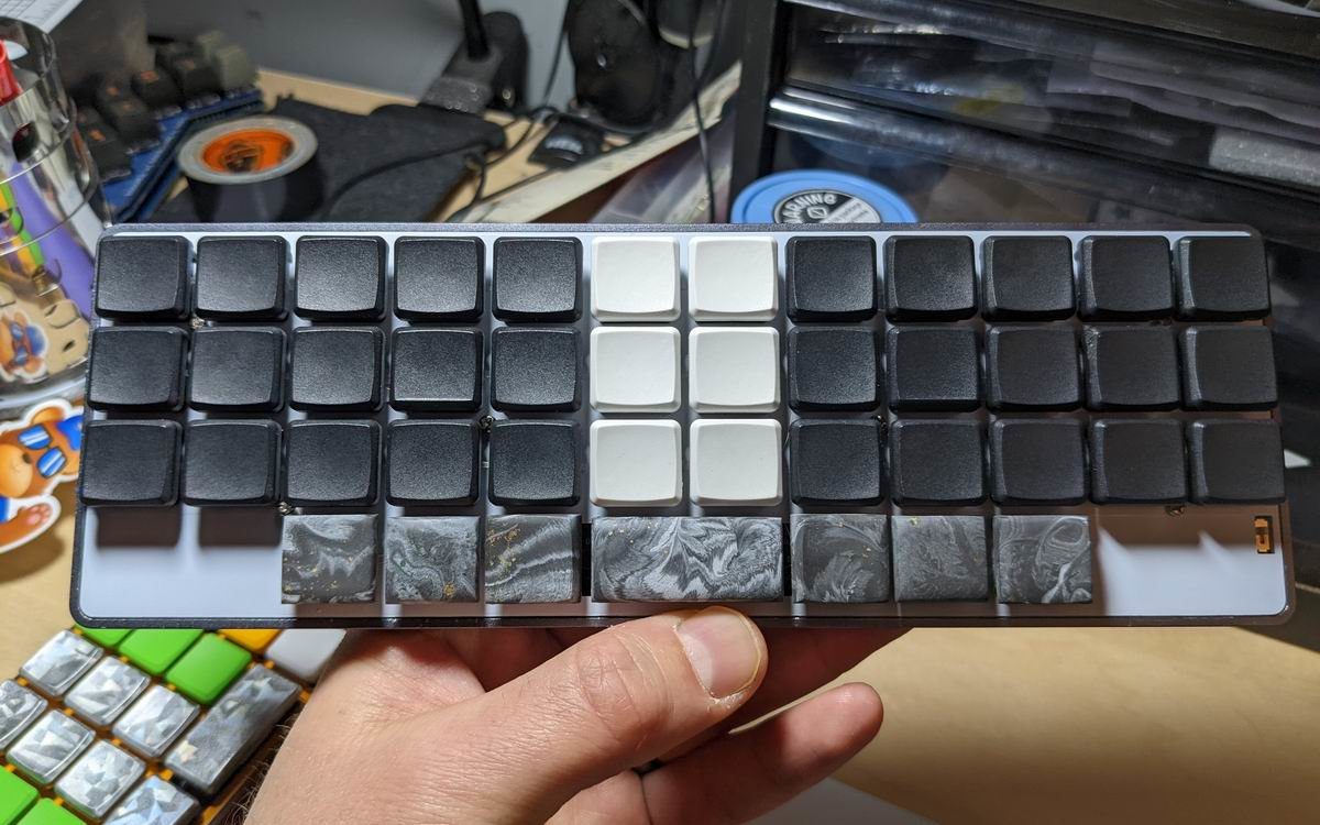
Written on a revxlp prototype, a variant of the reviung41 keyboard, but low profile, and using the XIAO footprint of controllers. This particular build sports the Seeed XIAO BLE, Choc Sunset switches, and LDSA keycaps.References
- ZMK Discord: https://zmk.dev/community/discord/invite
- ZMK Design Guide: https://github.com/ebastler/zmk-designguide
- ai03 PCB Guide: https://wiki.ai03.com/books/pcb-design
- ZMK Power Profiler: https://zmk.dev/power-profiler

Pete Johanson (40)
petejohansonLocation Full time RV'ing across the US Description Firmware developer and keyboard designer Occupation Embedded engineer, designer Joined 2020 Niche Wireless, low profile, 34-keys, unibody splits Fav. switch Chocs (Sunsets and 30g whites) Fav. profile Chicago Steno, LDSA, MBK Layout Colemak DH Other hobbies disc golf Links https://petejohanson.dev, https://github.com/sponsors/petejohanson/, @[email protected] Published on Wed 7th Dec 2022. Featured in KBD #106.
Related

Engikeeb
Engikeeb is an experimental ultra-low-cost approach to keyboard design – by customMK.
Charlieflex keyboard
Chad Transtrum's nice unibody split with encoder: the Charlieflex.
n36tsu
N36tsu by n1tsu. A low-profile split with PG1316S switches.
DaNumPad
Source files of Tweetydabirdie's DaNumPad are available on GitHub.
MiniNova
Tony Jeffree's MiniNova is a cute 30% staggered keyboard with exposed diodes.


